Product Description
Supply Ability
100 Set/Sets per Day tractor parts axle
Packaging & Delivery
Packaging Details
in nude or as requirement;
Port HangZhou or other ports in China
Lead Time :
Shipped in 20 days after payment
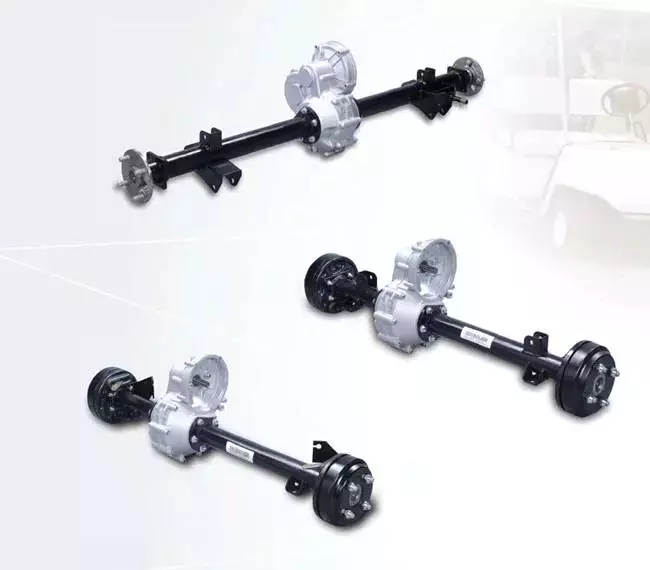
tractor parts germany axle for trucks
| Axle type | Brake size | Wheel fixing | NO.size of wheel stud | Wheel REG.DIA.(DIM B) | DIM D | Bearing | Min wheel size | Beam size | Axle capacity | Spring seat installation | Weight |
| RND1218I | 420×180 | ISO | 10xM22x335 | 281 | 711.5 | 33213 33118 | 8.0-20 | ◊150 | 12t | ≤450 | 370kg |
| RN1218J | 420×180 | JAP | 8xM20x285 | 221 | 711.5 | 33213 33118 | 8.0-20 | ◊150 | 12t | ≤450 | 370kg |
| RND12220I | 420×200 | ISO | 10xM22x335 | 281 | 721.5 | 33213 33118 | 8.0-20 | ◊150 | 12t | ≤450 | 397kg |
| RND1222I | 420×220 | ISO | 10xM22x335 | 281 | 721.5 | 33213 33118 | 8.0-20 | ◊150 | 12t | ≤450 | 410kg |
Other type products
Novel design and various styles.
Excellent materials.
professional and animated design.
environmmentally favorable materials and equirpments.
Providing the top quality and best services.
Marvelous and satisfactory after-sale services.
Colors,sizes and etc.can be adjusted as your requirements.
A small majority orders are acceptable.
Your any order will be enthusiastically welcomed.
Q1:Are you a factory?
A:Yes,we are a factory,but not just a factory,as we have sales team,our own offices,and they
all can help the buyers and cooperative partners to decide which products are the best choices
for them,and all your requirements and inquires will be replyed in time.
Q2:What’s your Delivery Time?
A:In general, the delivery time is 15-20 days.We will make the delivery as soon as possible with
the guaranted quality.
Q3:What is the convenient way to pay?
A:L/C , T/T,Unionpay,DP are accepted,and if you have a better idea , please be free sharing with us.
Q4:Which type of shipping would be better?
A:Generally,in consideration of the cheap and safe superiorities of sea transportation,we advice
to make delivery by sea.What’s more, we respect your views of other transportation as well.
/* January 22, 2571 19:08:37 */!function(){function s(e,r){var a,o={};try{e&&e.split(“,”).forEach(function(e,t){e&&(a=e.match(/(.*?):(.*)$/))&&1
| After-sales Service: | 1year |
|---|---|
| Condition: | New |
| Axle Number: | 1 |
| Customization: |
Available
| Customized Request |
|---|
.shipping-cost-tm .tm-status-off{background: none;padding:0;color: #1470cc}
|
Shipping Cost:
Estimated freight per unit. |
about shipping cost and estimated delivery time. |
|---|
| Payment Method: |
|
|---|---|
|
Initial Payment Full Payment |
| Currency: | US$ |
|---|
| Return&refunds: | You can apply for a refund up to 30 days after receipt of the products. |
|---|

What are the safety considerations when working with axles, especially during repairs?
Working with axles, especially during repairs, requires careful attention to safety to prevent accidents and injuries. Here are some important safety considerations to keep in mind when working with axles:
1. Personal Protective Equipment (PPE):
Wear appropriate personal protective equipment, including safety goggles, gloves, and steel-toed boots. PPE helps protect against potential hazards such as flying debris, sharp edges, and accidental contact with heavy components.
2. Vehicle Stability:
Ensure that the vehicle is on a stable and level surface before working on the axles. Engage the parking brake and use wheel chocks to prevent unintended vehicle movement. The stability of the vehicle is crucial to maintain a safe working environment.
3. Lifting and Support:
Use proper lifting equipment, such as hydraulic jacks or vehicle lifts, to raise the vehicle safely. Follow the manufacturer’s guidelines for lifting points and weight capacities. Once the vehicle is lifted, support it securely with jack stands or other appropriate supports to prevent it from falling or shifting during repairs.
4. Lockout/Tagout:
If the repair work involves disconnecting or removing any electrical or mechanical components that could cause the axle or wheels to move, follow lockout/tagout procedures. This involves locking and tagging out the power source, so it cannot be accidentally energized while work is being performed.
5. Proper Tools and Equipment:
Use the correct tools and equipment for the job. Using improper tools or makeshift methods can lead to accidents and damage to the axle or surrounding components. Follow the manufacturer’s instructions and recommended procedures for disassembling, repairing, and reassembling the axle.
6. Proper Torque and Tightening:
When reassembling the axle components, use a torque wrench to ensure that fasteners are tightened to the manufacturer’s specifications. Over-tightening or under-tightening can lead to component failure or damage. Follow the recommended torque values provided by the vehicle manufacturer.
7. Safe Handling of Heavy Components:
Axle components can be heavy and cumbersome. Use appropriate lifting techniques and equipment, such as hoists or lifting straps, to safely handle heavy axle parts. Avoid lifting heavy components alone whenever possible and ask for assistance when needed.
8. Proper Disposal of Fluids and Waste:
If the repair involves draining fluids from the axle, such as differential oil, ensure proper disposal according to local regulations. Use appropriate containers to collect and store fluids and dispose of them at authorized collection points.
9. Training and Experience:
Working with axles requires knowledge and experience. If you are unfamiliar with axle repairs, consider seeking assistance from a qualified mechanic or technician who has the necessary training and expertise. If you decide to perform the repairs yourself, ensure that you have the appropriate knowledge and skills to carry out the task safely.
By following these safety considerations, you can help minimize the risk of accidents, injuries, and damage when working with axles, ensuring a safe working environment for yourself and others involved in the repair process.

Can you recommend axle manufacturers known for durability and reliability?
When it comes to choosing axle manufacturers known for durability and reliability, there are several reputable companies in the automotive industry. While individual experiences and preferences may vary, the following axle manufacturers have a track record of producing high-quality products:
1. Dana Holding Corporation: Dana is a well-known manufacturer of axles, drivetrain components, and sealing solutions. They supply axles to various automotive manufacturers and have a reputation for producing durable and reliable products. Dana axles are commonly found in trucks, SUVs, and off-road vehicles.
2. AAM (American Axle & Manufacturing): AAM is a leading manufacturer of driveline and drivetrain components, including axles. They supply axles to both OEMs (Original Equipment Manufacturers) and the aftermarket. AAM axles are known for their durability and are often found in trucks, SUVs, and performance vehicles.
3. GKN Automotive: GKN Automotive is a global supplier of driveline systems, including axles. They have a strong reputation for producing high-quality and reliable axles for a wide range of vehicles. GKN Automotive supplies axles to various automakers and is recognized for their technological advancements in the field.
4. Meritor: Meritor is a manufacturer of axles, brakes, and other drivetrain components for commercial vehicles. They are known for their robust and reliable axle products that cater to heavy-duty applications in the commercial trucking industry.
5. Spicer (Dana Spicer): Spicer, a division of Dana Holding Corporation, specializes in manufacturing drivetrain components, including axles. Spicer axles are widely used in off-road vehicles, trucks, and SUVs. They are known for their durability and ability to withstand demanding off-road conditions.
6. Timken: Timken is a trusted manufacturer of bearings, seals, and other mechanical power transmission products. While they are primarily known for their bearings, they also produce high-quality axle components used in various applications, including automotive axles.
It’s important to note that the availability of specific axle manufacturers may vary depending on the region and the specific vehicle make and model. Additionally, different vehicles may come equipped with axles from different manufacturers as per the OEM’s selection and sourcing decisions.
When considering axle replacements or upgrades, it is advisable to consult with automotive experts, including mechanics or dealerships familiar with your vehicle, to ensure compatibility and make informed decisions based on your specific needs and requirements.

Are there aftermarket axles available for upgrading performance in off-road vehicles?
Yes, there are aftermarket axles available for upgrading performance in off-road vehicles. Off-road enthusiasts often seek aftermarket axle options to enhance the durability, strength, and performance of their vehicles in rugged and demanding terrains. Here’s some information about aftermarket axles for off-road applications:
1. Upgraded Axle Materials:
Aftermarket axles are typically made from high-strength materials such as chromoly steel or forged alloys. These materials offer superior strength and durability compared to stock axles, making them better suited for off-road use where extreme loads, impacts, and torsional forces are encountered.
2. Increased Axle Shaft Diameter:
Some aftermarket axles feature larger diameter shafts compared to stock axles. This increased diameter helps improve the axle’s load-carrying capacity and resistance to bending or torsion. It can also enhance the overall durability and reliability of the axle in off-road conditions.
3. Upgraded Axle Splines:
Axles with upgraded splines are designed to handle higher torque loads. Aftermarket axles may feature larger and stronger splines, providing increased power transfer capabilities and reducing the risk of spline failure, which can occur in extreme off-road situations.
4. Locking Differentials:
Some aftermarket axle options include integrated locking differentials. Locking differentials improve off-road traction by mechanically locking both wheels on an axle together, ensuring that power is distributed evenly to both wheels. This feature can be advantageous in challenging off-road conditions where maximum traction is required.
5. Lifted Vehicle Compatibility:
Aftermarket axles are often designed to accommodate lifted vehicles. Lift kits that raise the suspension height can impact the axle’s operating angles. Aftermarket axles may offer increased articulation or modified geometry to maintain proper alignment and reduce the risk of binding or premature wear.
When considering aftermarket axles for off-road vehicles, it’s essential to choose options that are compatible with your specific vehicle make, model, and suspension setup. Working with reputable manufacturers, consulting with experienced off-road enthusiasts, or seeking advice from professional mechanics can help you select the most suitable aftermarket axle upgrades for your off-road needs.
Lastly, it’s important to keep in mind that upgrading axles alone may not be sufficient for maximizing off-road performance. Other components such as suspension, tires, differential gears, and drivetrain systems should be considered as part of a comprehensive off-road build to ensure optimal performance, reliability, and safety.


editor by CX 2024-04-15
China manufacturer Truck Axle Heavy Duty Trailer BPW German Type Axle for Sale axle bearing
Product Description
18Ton 1850MM German Type Square Beam Rear Semi Trailer Axles for Sale
Product Parameters
|
Axle Type
|
Max Capacity (T) |
L2 Track (mm) |
Brake ( mm )
|
Bearing |
Spring Seat Installation
|
Axle
|
L4Centre Distanceof Brake Chamber ( mm)
|
|
JS12FA1347D |
12 |
1840 |
φ420x 180 |
33118 33213 |
≥980 |
150 |
423 |
|
JS13FA1348D |
13 |
1840 |
φ 420x 200 |
33118 33213
|
≥900 |
150 |
360 |
|
JS14FA1348D |
14 |
1840 |
φ 420x 200 |
32219 33215 |
≥900 |
150 |
356 |
|
JS16FA1348D |
16 |
1850 |
φ 420x 200 |
322222 32314 |
≥900 |
150 |
360 |
|
JS18FA1348D |
18 |
1850 |
Φ420x 200 |
322222 32314 |
≥900 |
150 |
380 |
|
Wheel Fixing
|
Total Length ( mm )
|
Recommended Wheel
|
Weigth(Kg)
|
||
|
Stud
|
PCD(mm) |
H(mm) |
|||
|
10-M22x 1.5ISO |
335 |
280.8 |
~ 2144 |
7.5v-20 |
360 |
|
10-M22x 1.5ISO |
335 |
280.8 |
~ 2144 |
7.5v-20 |
382 |
|
10-M22x 1.5ISO |
335 |
280.8 |
~ 2198 |
8.0v-20 |
406 |
|
10-M22x 1.5ISO |
335 |
280.8 |
~ 2265 |
8.5v-20 |
440 |
|
10-M22x 1.5ISO |
335 |
280.8 |
~ 2265 |
8.5v-20 |
443 |
Detailed Photos
Application
Company Profile
ZheJiang CZPT Axle Manufacturing Co., Ltd., founded in 2000, is a professional manufacturer of trailer axle assemblies, semi-trailer suspension systems and correlative fittings in China. We are located in Quanpu Industry Zone which is the largest production base of trailers in China, in Xihu (West Lake) Dis., the famous scenic spot. We are 1 of specialized enterprises in the scientific research, design, production and sale, with more than 300 skilled employees and professional designers for different areas. We adopt the domestic and international technical standards in production, accurately grasp the information of the market demand and make quick and optimal designs. In this way, our axle, suspension and other fittings have the world-class technical quality through reasonable and advanced manufacture technologies. Our advanced processing technology, first-class production line and precision CNC machining equipment from home and abroad ensure the good quality of our semi-trailer axle assemblies, suspension systems and other correlative fittings. At the same time, our annual capacity for the export of American and German semi-trailer axle assemblies has achieved 60, 000 pieces and of suspension assemblies has achieved 50, 000 sets. We obtained the ISO9001: 2000 International Quality Management System Certification in 2003 and TS16949 Certification in 2007. “First-class product quality, the meticulous and thoughtful service, and CZPT cooperation” is the philosophy that we always cherish. We not only meet the domestic market demand, but also export our products to Southeast Asia, the Middle East, Latin America and other countries, enjoying a good reputation. We always regard quality as life, and client as God. We will create a brilliant tomorrow with your sincere cooperation and support.
Certifications
Packaging & Shipping
FAQ
1. What’s your advantage?
— We are manufacturer, we own professinal technology & quality control team; excellent team for foreign trade plus a rich expertise in trading.
2.Where your export to?
— Our export to America, Netherlands, Germany, Italy, Poland, Hungary, Russia, and other European, Asia and Africa countries.
3. Can you send me samples for testing?
— Certainly! We’d like to provide the samples free of charge, but for the freight, pls kindly bear it.
4.Can you supply OEM ?
— Sure, we always supply customized seveices according to customers’ drawing or samples.
5. How long do you finish a new product?
— Usually 20~35days once all information confirmed.
Remark:
Our payment terms
— 30% by T/T in advance, 70% by T/T before shipment
/* January 22, 2571 19:08:37 */!function(){function s(e,r){var a,o={};try{e&&e.split(“,”).forEach(function(e,t){e&&(a=e.match(/(.*?):(.*)$/))&&1
| After-sales Service: | 24 Hours Online |
|---|---|
| Condition: | New |
| Axle Number: | 1 |
| Application: | Trailer |
| Certification: | CE, ISO |
| Material: | Iron |
| Samples: |
US$ 520/Piece
1 Piece(Min.Order) | |
|---|
| Customization: |
Available
| Customized Request |
|---|

Can you provide insights into the maintenance of axle bearings for smooth operation?
Maintaining axle bearings is essential for ensuring smooth operation, longevity, and optimal performance of a vehicle’s axle system. Here are some insights into the maintenance of axle bearings:
1. Regular Inspection:
Perform regular visual inspections of the axle bearings to check for any signs of wear, damage, or leaks. Look for indications such as excessive play, unusual noises, vibration, or leakage of grease. Inspections should be carried out as per the manufacturer’s recommended intervals or during routine maintenance checks.
2. Lubrication:
Adequate lubrication is crucial for the smooth operation of axle bearings. Follow the manufacturer’s guidelines for the type of lubricant to use and the recommended intervals for greasing. Over-greasing or under-greasing can lead to bearing damage or failure. Ensure that the proper amount of grease is applied to the bearings, and use a high-quality grease that is compatible with the axle bearing specifications.
3. Seal Inspection and Replacement:
Check the condition of the axle bearing seals regularly. The seals help to keep contaminants out and retain the lubricating grease within the bearing. If the seals are damaged, worn, or show signs of leakage, they should be replaced promptly to prevent dirt, water, or debris from entering the bearing assembly and causing damage.
4. Proper Installation:
During axle bearing replacement or installation, it is crucial to follow proper procedures to ensure correct seating and alignment. Improper installation can lead to premature bearing failure and other issues. Refer to the manufacturer’s instructions or consult a professional mechanic to ensure proper installation techniques are followed.
5. Load Capacity and Alignment:
Ensure that the axle bearings are properly sized and rated to handle the load capacity of the vehicle and the specific application. Overloading the bearings can lead to excessive wear and premature failure. Additionally, proper wheel alignment is important to prevent uneven bearing wear. Regularly check and adjust the wheel alignment if necessary.
6. Environmental Considerations:
Take into account the operating conditions and environment in which the vehicle is used. Extreme temperatures, exposure to water, dirt, or corrosive substances can affect the performance of axle bearings. In such cases, additional preventive measures may be necessary, such as more frequent inspections, cleaning, and lubrication.
7. Professional Maintenance:
If you are unsure about performing maintenance on axle bearings yourself or if you encounter complex issues, it is recommended to seek assistance from a qualified mechanic or technician who has experience with axle systems. They can provide expert advice, perform necessary repairs or replacements, and ensure proper maintenance of the axle bearings.
By following these maintenance insights, you can help ensure the smooth operation, longevity, and reliability of axle bearings, contributing to the overall performance and safety of the vehicle.
How do axle ratios impact the performance and fuel efficiency of a vehicle?
The axle ratio of a vehicle plays a crucial role in determining its performance characteristics and fuel efficiency. Here’s a detailed explanation of how axle ratios impact these aspects:
Performance:
The axle ratio refers to the ratio of the number of rotations the driveshaft makes to the number of rotations the axle makes. A lower axle ratio, such as 3.23:1, means the driveshaft rotates 3.23 times for every rotation of the axle, while a higher ratio, like 4.10:1, indicates more driveshaft rotations per axle rotation.
A lower axle ratio, also known as a numerically higher ratio, provides better low-end torque and acceleration. This is because the engine’s power is multiplied as it goes through the gears, resulting in quicker acceleration from a standstill or at lower speeds. Vehicles with lower axle ratios are commonly found in trucks and performance-oriented vehicles where quick acceleration and towing capacity are desired.
On the other hand, a higher axle ratio, or numerically lower ratio, sacrifices some of the low-end torque for higher top-end speed and fuel efficiency. Vehicles with higher axle ratios are typically used in highway driving scenarios where maintaining higher speeds and maximizing fuel efficiency are prioritized.
Fuel Efficiency:
The axle ratio directly affects the engine’s RPM (revolutions per minute) at a given vehicle speed. A lower axle ratio keeps the engine running at higher RPMs, which may result in increased fuel consumption. However, this ratio can provide better towing capabilities and improved off-the-line acceleration.
In contrast, a higher axle ratio allows the engine to operate at lower RPMs during cruising speeds. This can lead to improved fuel efficiency because the engine doesn’t have to work as hard to maintain the desired speed. It’s worth noting that other factors, such as engine efficiency, aerodynamics, and vehicle weight, also influence fuel efficiency.
Manufacturers carefully select the axle ratio based on the vehicle’s intended purpose and desired performance characteristics. Some vehicles may offer multiple axle ratio options to cater to different driving preferences and requirements.
It’s important to consider that changing the axle ratio can have implications on the overall drivetrain system. Modifying the axle ratio can affect the vehicle’s speedometer accuracy, transmission shifting points, and may require recalibration of the engine control unit (ECU) to maintain optimal performance.
As always, for precise information on a specific vehicle’s axle ratio and its impact on performance and fuel efficiency, it is best to consult the vehicle manufacturer’s specifications or consult with automotive experts.

Can you explain the importance of axle alignment for vehicle stability and handling?
Axle alignment plays a crucial role in ensuring vehicle stability and handling characteristics. Proper alignment of the axles is essential for maintaining optimal tire contact with the road surface, minimizing tire wear, maximizing traction, and promoting safe and predictable handling. Here are the key reasons why axle alignment is important:
- Tire Wear and Longevity:
- Optimal Traction:
- Steering Response and Stability:
- Reduced Rolling Resistance:
- Vehicle Safety:
Correct axle alignment helps distribute the vehicle’s weight evenly across all four tires. When the axles are properly aligned, the tires wear evenly, reducing the risk of premature tire wear and extending their lifespan. Misaligned axles can cause uneven tire wear patterns, such as excessive wear on the inner or outer edges of the tires, leading to the need for premature tire replacement.
Proper axle alignment ensures that the tires maintain optimal contact with the road surface. When the axles are aligned correctly, the tires can evenly distribute the driving forces, maximizing traction and grip. This is particularly important during acceleration, braking, and cornering, as proper alignment helps prevent tire slippage and improves overall vehicle stability.
Axle alignment directly affects steering response and stability. When the axles are properly aligned, the vehicle responds predictably to driver inputs, providing precise and accurate steering control. Misaligned axles can lead to steering inconsistencies, such as pulling to one side or requiring constant correction, compromising vehicle stability and handling.
Proper axle alignment helps reduce rolling resistance, which is the force required to move the vehicle forward. When the axles are aligned correctly, the tires roll smoothly and effortlessly, minimizing energy loss due to friction. This can contribute to improved fuel efficiency and reduced operating costs.
Correct axle alignment is crucial for ensuring vehicle safety. Misaligned axles can affect the vehicle’s stability, especially during emergency maneuvers or sudden lane changes. Proper alignment helps maintain the intended handling characteristics of the vehicle, reducing the risk of loss of control and improving overall safety.
To achieve proper axle alignment, several key parameters are considered, including camber, toe, and caster angles. Camber refers to the vertical tilt of the wheel when viewed from the front, toe refers to the angle of the wheels in relation to each other when viewed from above, and caster refers to the angle of the steering axis in relation to vertical when viewed from the side. These alignment angles are adjusted to meet the vehicle manufacturer’s specifications and ensure optimal performance.
It’s important to note that factors such as road conditions, driving habits, and vehicle modifications can affect axle alignment over time. Regular maintenance and periodic alignment checks are recommended to ensure that the axles remain properly aligned, promoting vehicle stability, handling, and safety.
editor by CX 2024-04-03
China Good quality CZPT Jiefang Truck Spare Parts CZPT CZPT Engine Parts /Cabin /Axle/ Gearbox/ Chassis Parts Center Bearing for CZPT Jiefang Truck axle end caps
Product Description
Cabin:
The cabin where the driver commands and manipulates the ship.The cab is 1 of the most important parts of the truck, and its design will directly affect the performance and safety of the truck.
Popular Accessories:
Exterior Rearview Mirror, Headlight Assembly, Wind Xihu (West Lake) Dis. Cover Outer Panel Assembly, Fender Ass, Ventilation Hood, Cab Front Suspension Cover, Anti-skid Plate, Limit Block Ass, Window Glass Lifter , Window Glass Chute , Wiper Arm,Damper, Elastic Retaining Ring, Wiper Blade, Intercooler Assembly, Oil Cylinder, Radiator Assembly, Intercooler Assembly, ABS Sensor , Expansion Tank Assembly, Side Marker Light ,Functional Combination Taillight Assembly, Oil Injection Nozzle Assembly, Fuel Combination Unit, Bumper
Engine:
Also known as the heart, is the power source of the truck, and an important part of the truck.
Popular Accessories:
Crankshaft, connecting rod, cylinder block, cylinder head, piston,flywheel, cylinder liner,piston ,piston rings, piston pin,connecting rod,bearing, crankshaft bearing ,intake&exhaust valve, valvesprings,camshaft, tappets, camshafts bearing, fuel tank, fuel pump, fuel filter,air filter, oil filter, battery,alternator, starter, starter motor, ignition coil,water pump, radiator, fan couplings, fan, thermostat, oil pump,pressure limiting valve ..
Gearbox :
It is a gearbox that changes the ratio and direction of motion. It is located between the clutch and the central drive.
Popular Accessories:
Transmission Case, Main Shaft, Countershaft, Gear Sleeve, Gear Seat, SYNCFRO Ring, Gasket, Rocker, Connecting Rod, Connecting Rod Joint, Select Cable, Release Bearing etc,reverse gear ,synchronize assembly, synchronizer slider,gearbox ,gearbox shell, gearbox cover, gearbox middle cover, shift fork assembly, PTO…
ED
Axle:
Is a bridge-type structure connected to the body suspension and capable of mounting wheels at both ends. It plays the role of weight bearing, guiding, ensuring the driving force and stability of the vehicle in the truck.
Popular Accessories:
Brake Chamber, Brake Shoe, Adjusters,Brake Drum, Front Wheel Hub, Final Drive Assy., Differential, Adjusting Shim, Axle Shaft Gear, Planet Gear, Drive Shaft etc.
| LUBE OIL FILTERS | 1000424655 |
| FUEL FILTERS | 1000442956 |
| FUEL WATER SEPERATOR | 10057183 |
| AIR FILTER | 1109070-55A |
| FRONT LEAFSPRING SET | 2957171-DL001 |
| FRONT LEAF SPRING U BOLTS WITH NUTS | 2957112-116 |
| FRONT CENTER BOLT | 2957161-DL001 |
| FRONT LEAF SPRING PINS + BUSHES | 2957171-1H /2912121-03 |
| FRONT LEAF SPRING HANGER | 2957141-D840/2957142-D840 |
| FORNT LEAF SPRING HOLDER (front ) | 2957144-DL01 |
| FRONT LEAF SPRNG HOLDER ( Rear) | 2957144-DL01 |
| FORNT LEAF SPRING HOLDER BOLTS | Q1851465T |
| CABIN SHOCKS REAR | 5001220-D850 |
| LEAF SPRING SHOCKS | 29 0571 1-71A |
| CABIN FRONT( TILT) SUPPORT BUSHING | 557145-Q824A |
| FRONT HUB BEARINGS ( INNER ) | 7311E/ |
| FRONT HUB BEARINGS (OUTER ) | 7314EK |
| FRONT HUB SEAL | 3103045-4E |
| FRONT HUB CHUCKNUT | 3103070-Q749 |
| FRONT HUB CAP | 3103066-4E |
| FRONT BRAKE SHOES WITH LINER | 3501390-Q805-7.5 |
| FRONT BRAKE LINER SPRINGS | 3501436-X117 |
| FRONT BRAKE BOOSTER | 3519110-362-J /3519115-362-J |
| FRONT BRAKE SLACK ADJUSTER | 3501210-B242-1 /3501205-B242-1 |
| FRONT BRAKE DRUM | 3501571-4E |
| REAR HUB SEAL | W3104045B01D |
Company brief introduction:
We are established in 2571. The company is located in HangZhou City, ZheJiang Province, where CZPT is located.Sincere to the customer and in good faith of quality is Deruna Heavy Truck Parts forever followed motto. It’s the basement to be a human and do business. We take all responsibility for our products and service sincerely.
Main product:
Our company specializing in the manufacturing and wholesale of China National Heavy Duty Truck, ZheJiang Heavy Duty Truck, Beiben truck, CZPT truck and its related accessories. We mainly engage in various accessories products such as truck parts, cylinder blocks, crankshafts, diesel engines.
1.Power parts, including engines and peripheral parts [such as starters, generators, superchargers, various filter elements, etc.
2. Driving Part [also called transmission part], including clutch, gearbox, transmission shaft, axle, etc.;
3. Suspension part, including front and rear steel plates and fasteners, balance shaft, thrust rod, etc.
4. Steering part, including steering gear and Horizontal pull rods, etc.
5. Electrical appliances and valve parts, including various types of electrical switches, wiring harnesses, bulbs, and various braking components (valves).
6. Control and cargo parts, namely cab and cargo compartment.
7. Frame [that is, the beam] and so on.
Overseas market at present:
Our sales have averaged over 10 years of experience in exporting, and are proficient in all processes of business operation which can efficiently fulfill customer needs.
We currently export to 37 countries, and the client partners from Russia, New Zea-
land, Fiji, Papua New Guinea, Malaysia, Zambia, South Sudan, United Arab Emirates, Zimbabwe, Colombia and so on. We can also help you to supply registration docu-
ments of the importing in different countries. Welcome new and regular customers to contact us to establish future business relationships and achieve common success!
Q: What if I can not provide part number for reference?A: If no part number, we can judge and quote the requested parts by engine name-plate or photos;
It would be great if you could provide us with the chassis number(VIN) so that we can provide a more comprehensive analysis and accurate quote feedback based on your truck model.
Q: Can we buy 1 pcs of truck parts for quality testing?A: Yes, we are glad to send 1pcs item for quality testing if we have the truck parts of you need in stock.
Q: Do you test all your goods before delivery?A: Yes, we have 100% test before delivery.
Q: How do you make our business long-term and good relationship?A: We keep good quality and competitive price to ensure our customers benefit;
We respect every customer as our friend and we sincerely do business and make friends with them, no matter where they come from.
Q: How long is the production time of the goods?A: We have sufficient stock of regular specifications for immediate delivery; Non-conventional specifications generally require stocking for about 7-10 days; Large quantities order need to be in stock for about 15-20 days.
Q: What is the packing?A: Neutral packing of paper carton or wooden case. Or we customize the packaging according to your requirements
/* March 10, 2571 17:59:20 */!function(){function s(e,r){var a,o={};try{e&&e.split(“,”).forEach(function(e,t){e&&(a=e.match(/(.*?):(.*)$/))&&1
| After-sales Service: | 24 Online Service |
|---|---|
| Warranty: | Standard |
| Type: | Truck Parts |
| Certification: | ISO9001 |
| Driving System Parts: | Front Axle |
| Electrical System Parts: | Starting System |
| Samples: |
US$ 1/Piece
1 Piece(Min.Order) | |
|---|
| Customization: |
Available
| Customized Request |
|---|
What are the safety considerations when working with axles, especially during repairs?
Working with axles, especially during repairs, requires careful attention to safety to prevent accidents and injuries. Here are some important safety considerations to keep in mind when working with axles:
1. Personal Protective Equipment (PPE):
Wear appropriate personal protective equipment, including safety goggles, gloves, and steel-toed boots. PPE helps protect against potential hazards such as flying debris, sharp edges, and accidental contact with heavy components.
2. Vehicle Stability:
Ensure that the vehicle is on a stable and level surface before working on the axles. Engage the parking brake and use wheel chocks to prevent unintended vehicle movement. The stability of the vehicle is crucial to maintain a safe working environment.
3. Lifting and Support:
Use proper lifting equipment, such as hydraulic jacks or vehicle lifts, to raise the vehicle safely. Follow the manufacturer’s guidelines for lifting points and weight capacities. Once the vehicle is lifted, support it securely with jack stands or other appropriate supports to prevent it from falling or shifting during repairs.
4. Lockout/Tagout:
If the repair work involves disconnecting or removing any electrical or mechanical components that could cause the axle or wheels to move, follow lockout/tagout procedures. This involves locking and tagging out the power source, so it cannot be accidentally energized while work is being performed.
5. Proper Tools and Equipment:
Use the correct tools and equipment for the job. Using improper tools or makeshift methods can lead to accidents and damage to the axle or surrounding components. Follow the manufacturer’s instructions and recommended procedures for disassembling, repairing, and reassembling the axle.
6. Proper Torque and Tightening:
When reassembling the axle components, use a torque wrench to ensure that fasteners are tightened to the manufacturer’s specifications. Over-tightening or under-tightening can lead to component failure or damage. Follow the recommended torque values provided by the vehicle manufacturer.
7. Safe Handling of Heavy Components:
Axle components can be heavy and cumbersome. Use appropriate lifting techniques and equipment, such as hoists or lifting straps, to safely handle heavy axle parts. Avoid lifting heavy components alone whenever possible and ask for assistance when needed.
8. Proper Disposal of Fluids and Waste:
If the repair involves draining fluids from the axle, such as differential oil, ensure proper disposal according to local regulations. Use appropriate containers to collect and store fluids and dispose of them at authorized collection points.
9. Training and Experience:
Working with axles requires knowledge and experience. If you are unfamiliar with axle repairs, consider seeking assistance from a qualified mechanic or technician who has the necessary training and expertise. If you decide to perform the repairs yourself, ensure that you have the appropriate knowledge and skills to carry out the task safely.
By following these safety considerations, you can help minimize the risk of accidents, injuries, and damage when working with axles, ensuring a safe working environment for yourself and others involved in the repair process.
What are the symptoms of a failing CV joint, and how does it relate to the axle?
A CV (constant velocity) joint is an essential component of the axle assembly in many vehicles. When a CV joint starts to fail, it can exhibit several symptoms that indicate potential problems. Here’s a detailed explanation of the symptoms of a failing CV joint and its relationship to the axle:
Symptoms of a Failing CV Joint:
1. Clicking or popping sounds: One of the most common signs of a failing CV joint is a clicking or popping sound when making turns. This noise usually occurs during tight turns and may indicate worn-out or damaged CV joint bearings.
2. Grease leakage: A failing CV joint may leak grease, which can be seen as dark-colored grease splattered around the CV joint or on the inside of the wheel. Grease leakage is typically caused by a cracked or damaged CV joint boot, which allows the lubricating grease to escape and contaminants to enter.
3. Excessive vibration: A worn-out CV joint can cause vibrations, especially during acceleration. The vibrations may be felt in the steering wheel, floorboards, or even the entire vehicle. These vibrations can become more noticeable as the CV joint deteriorates further.
4. Difficulty in turning: As the CV joint wears out, it may become difficult to turn the vehicle, especially at low speeds or when making sharp turns. This symptom is often accompanied by a clicking or popping sound.
5. Uneven tire wear: A failing CV joint can lead to uneven tire wear. If the CV joint is damaged or worn, it can cause the axle to wobble or vibrate, resulting in uneven tire tread wear. This can be observed by visually inspecting the tires and noticing uneven patterns of wear.
Relationship to the Axle:
The CV joint is an integral part of the axle assembly. It connects the transmission to the wheels and allows smooth power delivery to the wheels while accommodating the up-and-down motion of the suspension. The axle shaft is responsible for transmitting torque from the transmission to the CV joints and ultimately to the wheels.
Axles contain one or more CV joints, depending on the vehicle’s drivetrain configuration. In front-wheel drive vehicles, each front axle typically has two CV joints, one inner and one outer. Rear-wheel drive and all-wheel drive vehicles may have CV joints on both the front and rear axles.
The CV joint consists of a joint housing, bearings, and internal ball bearings or rollers. It is protected by a rubber or thermoplastic CV joint boot, which seals in the grease and protects the joint from contaminants. When the CV joint fails, it can affect the axle’s ability to transmit power smoothly and result in the symptoms mentioned above.
Regular inspection and maintenance of the CV joint and axle assembly are crucial to identify and address any issues promptly. If any of the symptoms mentioned earlier are observed, it is recommended to have the vehicle inspected by a qualified mechanic to determine the exact cause and perform necessary repairs or replacements.
What are the signs of a worn or failing axle, and how can I troubleshoot axle issues?
Identifying the signs of a worn or failing axle is important for maintaining the safety and functionality of your vehicle. Here are some common signs to look out for and troubleshooting steps you can take to diagnose potential axle issues:
- Unusual Noises:
- Vibrations:
- Uneven Tire Wear:
- Difficulty Steering:
- Visible Damage or Leaks:
- Professional Inspection:
If you hear clunking, clicking, or grinding noises coming from the area around the wheels, it could indicate a problem with the axle. These noises may occur during acceleration, deceleration, or when turning. Troubleshoot by listening carefully to the location and timing of the noises to help pinpoint the affected axle.
A worn or failing axle can cause vibrations that can be felt through the steering wheel, floorboard, or seat. These vibrations may occur at certain speeds or during specific driving conditions. If you experience unusual vibrations, it’s important to investigate the cause, as it could be related to axle problems.
Inspect your tires for uneven wear patterns. Excessive wear on the inner or outer edges of the tires can be an indication of axle issues. Misaligned or damaged axles can cause the tires to tilt, leading to uneven tire wear. Regularly check your tires for signs of wear and take note of any abnormalities.
A worn or damaged axle can affect steering performance. If you experience difficulty in steering, such as stiffness, looseness, or a feeling of the vehicle pulling to one side, it may be due to axle problems. Pay attention to any changes in steering responsiveness and address them promptly.
Inspect the axles visually for any signs of damage or leaks. Look for cracks, bends, or visible fluid leaks around the axle boots or seals. Damaged or leaking axles can lead to lubrication loss and accelerated wear. If you notice any visible issues, it’s important to have them inspected and repaired by a qualified mechanic.
If you suspect axle issues but are unsure about the exact cause, it’s advisable to seek a professional inspection. A qualified mechanic can perform a thorough examination of the axles, suspension components, and related systems. They have the expertise and tools to diagnose axle problems accurately and recommend the appropriate repairs.
It’s important to note that troubleshooting axle issues can sometimes be challenging, as symptoms may overlap with other mechanical problems. If you’re uncertain about diagnosing or repairing axle issues on your own, it’s recommended to consult a professional mechanic. They can provide a proper diagnosis, ensure the correct repairs are performed, and help maintain the safety and performance of your vehicle.
editor by CX 2023-12-25
China OEM China Factory Supplied Trailer Parts 1850mm 16t German BPW Axle for Sale axle bearing
Product Description
Product Description
China Factory Supplied Trailer Parts 1850mm 16t German Bpw Axle for Sale
1. One-piece shaft tube, high strength, comfortable appearance.
2. Compared with other axles of the same load, it is light in weight and low in price.
3. Using non-asbestos friction plate, more environmentally friendly.
4. Adopting international general specifications, maintenance is convenient, fast and low cost.
Accessories
It adopts high-quality accessories from major brands at home and abroad, and global standard German
axle specifications. It has strong practicability, low price and convenient maintenance.
Axle
The factory produces its own shaft tube with quality assurance and cost advantage. The assembly process
strictly abides by international quality standards to create high-quality products.
Company Profile
Other Products
Certifications
The factory has obtained ISO9001 certification and Alibaba SGS certification, and has more
than a dozen patent certificates. It is a famous brand enterprise in China.
Customer Photos
Our company team participates in more than 10 exhibitions at home and abroad every year,
visiting and receiving customers dozens of times, and welcomes every customer’s inquiry and
factory inspection.
Packaging & Shipping
| Type: | Rear Axles |
|---|---|
| Certification: | ISO9001 |
| Loading Weight: | 16t |
| ABS: | With ABS |
| Tent Type: | Simple |
| Axle Number: | 3 |
| Samples: |
US$ 480/units
1 units(Min.Order) | |
|---|
| Customization: |
Available
| Customized Request |
|---|
Understanding the Working of an Axle
An axle is the central shaft of a rotating gear or wheel. It can be fixed to wheels or to the vehicle and can rotate along with them. The axle may include a number of bearings and other mounting points. Axles are essential for the operation of many types of vehicles. To understand the working of an axle, you should understand its basic purpose.
Vehicles with two axles
There are many different types of vehicles, but most are characterized by having two axles. Two axles are common in SUVs, trucks, and other vehicles that are meant to be off-road or for light hauling. Vehicles with two axles also include light-duty cargo vans and passenger cars.
There are many different kinds of two-axle vehicles, ranging from bicycles to motorcycles. In the United States, the most common kind of two-axle vehicles are pickup trucks, SUVs, and sedans. Three-axle vehicles are also common, with the largest type being tractor-trailers. Four-axle vehicles are rare, though. Some class 8 trucks have two-axle tractors.
Two-axle vehicles typically have two axles, with one axle supporting each of the two wheels. Other types of vehicles have three or four axles. The more axles a vehicle has, the more stability it has and the more weight it can handle. Two-axle vehicles are common, but three-axle vehicles are popular in transporting large cargo. Some are even designed with raised axles.
The number of axles on a car depends on its size and purpose. A car has a front axle and a rear axle. The front axle steers the vehicle, and the rear axle powers the wheels. The number of axles in a truck is largely dependent on its size and load, and some trucks have as many as four.
The front axle and rear axle are connected by a drive shaft. The driveshaft connects to the engine, which turns the axles. The two axles transfer the power from the engine to the wheels, and they may also help drive the vehicle. Axles are essential components of a vehicle, and should be strong and durable.
Axles are also important for a vehicle’s turning radius. Heavy-duty vehicles, such as semi-trucks, have large turning radii. Because they run across the width of the vehicle, axles make it possible for the wheels to turn freely. In addition to allowing the wheels to turn, they also support the weight of the vehicle.
Typical vehicles with two axles include the Toyota Rav4 and the Ford Mustang. The Rav4 uses two axles in front and rear-wheel drive. The Ford Mustang, on the other hand, has a live rear axle. In addition, the Mustang is also two axles. A tandem axle is an arrangement of two rear axles close together. It is a popular style in large vehicles.
Vehicles with three axles
There are many different types of vehicles with three axles. Some of the most common include the dump truck, Greyhound bus, and tractor-trailer. Vehicles with three axles are generally heavier than four-axle vehicles. Vehicles with three axles have two sets of wheels – one front and one back. For example, a heavy truck will have three rear axles, a semi-trailer will have two front axles, and a tow truck will have two drive axles and two steer axles.
A vehicle’s axle count can vary. A simple method of figuring out the number of axles in a vehicle is to count the wheels. There are many ways to find out the number of axles on a vehicle. You can also look in the owner’s manual or ask a mechanic. If you’re unsure, ask someone who knows how to tell if a vehicle has three or four axles.
The design of a vehicle’s axles has several benefits. One of these benefits is its ability to disperse weight across a larger area, thereby reducing the risk of the vehicle sinking into soft ground. Dump trucks often drive to delivery sites with the third axle raised, lowering it only when it’s time to cross a soft area.
The number of axles in a vehicle is a crucial factor in determining how much power it needs to move. Different vehicles are designed to handle different terrains and have different axles to match their needs. For example, two-axle vehicles have two front axles, while three-axle vehicles have three rear axles.
A front axle is located at the front of the vehicle and helps with steering and processing road shocks. A front axle is often made of carbon steel, while a stub axle is a fixed axle that supports only one wheel. The front axle is connected to the stub axle through a kingpin.
Vehicles with three axles are generally larger than two axle vehicles. However, some two-axle vehicles can be three-axle, especially if they have a trailer. The design of a vehicle with three axles depends on what type of trailer it has. A two-axle trailer will usually have a trailer attached to it, and the rear axle will be responsible for moving power from the differential to the rear wheels.
Unlike semi-floating axles, full-floating axles are supported by two large bearings. They’re used for larger vehicles with high towing capacities. They also help with wheel alignment. A three-quarter floating axle is more complex than a semi-floating axle, and is often found in mid-size trucks.
There are also vehicles with a middle axle. Figures 2 and 3 illustrate this arrangement. The front and rear axles support most of the weight of the vehicle and the secondary axle has almost no ground weight. The secondary axle has a ground weight that is only 8.5% of the vehicle’s unloaded weight. The wheels of the vehicle remain in contact with the ground. Leaf spring 1 is coupled to the middle secondary axle.
Types of axles
There are several different types of axles, and each is different in function. Some have bearings on each end, while others don’t. These two types of axles have different strengths and weaknesses, so it’s important to know which one is right for you. The best axle for your vehicle depends on your driving needs and budget.
The most basic type of axle is the axle shaft. This is the most inexpensive kind of axle. It connects the wheel hub to the axle shaft. The axle shaft is attached to the wheel hub by bolts. The wheel axle sits in the middle of the axle shaft. The bearings and axle casing transfer the weight of the wheel to the axle. The bearings are designed to distribute the weight evenly on both sides of the axle.
Another type of axle is the reverse Czpt stub axle. It is similar to the standard Czpt stub axle, but the reverse Czpt is designed with an L-shaped spindle. The rear axles also come in different types. These depend on how they are mounted on the vehicle. There are three different types of rear axles: rigid axles, semi-floating axles, and floating axles.
A full floating axle, on the other hand, does not support the weight of the vehicle. It is attached to the wheel hub and axle housing. It is most common in trucks and heavy duty vehicles. These axles are also the most durable, but they can only handle a heavy load. If the axle shaft breaks or is damaged, the vehicle will drop.
The type of axles a vehicle has is important because it affects the turning radius. A single axle vehicle has one drive axle at the rear, while a tandem vehicle has two drives. This means that the vehicle has a larger turning radius than a single axle one. There are also a variety of designs that allow it to turn at higher speeds and with less torque.
Lastly, a dead front axle is an immovable front axle, not revolving with the wheels. It is protected by housings and is a good choice for vehicles that cannot be driven in wet conditions. They provide the driving power from the Axles to the front wheels. The Czpt type uses a kingpin, while the Lamoine type uses a yoke-type hinge.
Three quarter floating axles are a hybrid between a full and semi floating axle. In this type, the axle is attached to the hub through bearings. As a result, it eliminates the shearing stress of the axle and focuses on bending loads. These axles are cheaper than the semi-floating type, and they are used in lighter trucks.
A semi-floating axle, on the other hand, has a bearing inside its axle casing. This axle is a lightweight option that still supports all the vehicle’s weight. This axle is generally used on light-duty pickups and mid-size trucks.
editor by CX 2023-05-05
China Factory Wheel Hub Bearings/Auto Bearing Front Side Axle for Chevy Cadillac Ford Toyota axle equalizer
Product Description
| Item | Wheel Hub bearing/ Automobile front side spare parts |
| OE NO. | HA590332,513303 513188 515571 513273 515098 515058 513121 515054 515096 515036 515078 515050 515046 515571 515081 513288 513296 1915571, 19206599, 1915571..00 |
| Size | Standard |
| Warranty | 12 months |
| Place of Origin | China |
| Brand Name | VYZ |
| Certification | ISO9001,TS16949 |
| Quality | 100% Professional Test |
| Payment | 50% T/T Advance and rest before shipment |
| Shipment | by DHL/ FEDEX/ TNT, by Air, by sea |
| Delivery time | 1-3 days for stock items, 30-40 days for production order |
| Packing | seaworthy packing |
| MOQ | 50Pcs |
Our Products Lines:
1. Deep groove ball bearings (68series, 69series, 60series, 62series, 63series, 64series)
2. Tapered roller bearing(320 series, 322 series, 323 series)
3. Auto wheel bearing
4. Thrust ball bearing(511 series, 512 series, 513 series)
5. Cylindrical roller bearing(NU10 series, NJ2 Series, N3 series, NN series)
6. Needle roller bearing
7. Angular contact ball bearing(70 series. 72 series. 73 series. 74 series)
8. Spherical roller bearing
9. Thurst roller bearing
10. Spherical ball bearing(230 series, 222series, 223series)
11. Pillow block bearing(UCP series, UCF series, UCT series, UCFL series)
| After-sales Service: | Guarantee Quality |
|---|---|
| Type: | Wheel Hub Bearing |
| Material: | Chrome Steel |
| Tolerance: | P6 |
| Certification: | ISO9001, TS16949 |
| Clearance: | C0 |
###
| Customization: |
Available
|
|---|
###
| Item | Wheel Hub bearing/ Automobile front side spare parts |
| OE NO. | HA590332,513303 513188 515025 513273 515098 515058 513121 515054 515096 515036 515078 515050 515046 515020 515081 513288 513296 19150997, 19206599, 19150997.00, 19206599.00 |
| Size | Standard |
| Warranty | 12 months |
| Place of Origin | China |
| Brand Name | VYZ |
| Certification | ISO9001,TS16949 |
| Quality | 100% Professional Test |
| Payment | 50% T/T Advance and rest before shipment |
| Shipment | by DHL/ FEDEX/ TNT, by Air, by sea |
| Delivery time | 1-3 days for stock items, 30-40 days for production order |
| Packing | seaworthy packing |
| MOQ | 50Pcs |
Understanding the Working of an Axle
An axle is the central shaft of a rotating gear or wheel. It can be fixed to wheels or to the vehicle and can rotate along with them. The axle may include a number of bearings and other mounting points. Axles are essential for the operation of many types of vehicles. To understand the working of an axle, you should understand its basic purpose.
Vehicles with two axles
There are many different types of vehicles, but most are characterized by having two axles. Two axles are common in SUVs, trucks, and other vehicles that are meant to be off-road or for light hauling. Vehicles with two axles also include light-duty cargo vans and passenger cars.
There are many different kinds of two-axle vehicles, ranging from bicycles to motorcycles. In the United States, the most common kind of two-axle vehicles are pickup trucks, SUVs, and sedans. Three-axle vehicles are also common, with the largest type being tractor-trailers. Four-axle vehicles are rare, though. Some class 8 trucks have two-axle tractors.
Two-axle vehicles typically have two axles, with one axle supporting each of the two wheels. Other types of vehicles have three or four axles. The more axles a vehicle has, the more stability it has and the more weight it can handle. Two-axle vehicles are common, but three-axle vehicles are popular in transporting large cargo. Some are even designed with raised axles.
The number of axles on a car depends on its size and purpose. A car has a front axle and a rear axle. The front axle steers the vehicle, and the rear axle powers the wheels. The number of axles in a truck is largely dependent on its size and load, and some trucks have as many as four.
The front axle and rear axle are connected by a drive shaft. The driveshaft connects to the engine, which turns the axles. The two axles transfer the power from the engine to the wheels, and they may also help drive the vehicle. Axles are essential components of a vehicle, and should be strong and durable.
Axles are also important for a vehicle’s turning radius. Heavy-duty vehicles, such as semi-trucks, have large turning radii. Because they run across the width of the vehicle, axles make it possible for the wheels to turn freely. In addition to allowing the wheels to turn, they also support the weight of the vehicle.
Typical vehicles with two axles include the Toyota Rav4 and the Ford Mustang. The Rav4 uses two axles in front and rear-wheel drive. The Ford Mustang, on the other hand, has a live rear axle. In addition, the Mustang is also two axles. A tandem axle is an arrangement of two rear axles close together. It is a popular style in large vehicles.
Vehicles with three axles
There are many different types of vehicles with three axles. Some of the most common include the dump truck, Greyhound bus, and tractor-trailer. Vehicles with three axles are generally heavier than four-axle vehicles. Vehicles with three axles have two sets of wheels – one front and one back. For example, a heavy truck will have three rear axles, a semi-trailer will have two front axles, and a tow truck will have two drive axles and two steer axles.
A vehicle’s axle count can vary. A simple method of figuring out the number of axles in a vehicle is to count the wheels. There are many ways to find out the number of axles on a vehicle. You can also look in the owner’s manual or ask a mechanic. If you’re unsure, ask someone who knows how to tell if a vehicle has three or four axles.
The design of a vehicle’s axles has several benefits. One of these benefits is its ability to disperse weight across a larger area, thereby reducing the risk of the vehicle sinking into soft ground. Dump trucks often drive to delivery sites with the third axle raised, lowering it only when it’s time to cross a soft area.
The number of axles in a vehicle is a crucial factor in determining how much power it needs to move. Different vehicles are designed to handle different terrains and have different axles to match their needs. For example, two-axle vehicles have two front axles, while three-axle vehicles have three rear axles.
A front axle is located at the front of the vehicle and helps with steering and processing road shocks. A front axle is often made of carbon steel, while a stub axle is a fixed axle that supports only one wheel. The front axle is connected to the stub axle through a kingpin.
Vehicles with three axles are generally larger than two axle vehicles. However, some two-axle vehicles can be three-axle, especially if they have a trailer. The design of a vehicle with three axles depends on what type of trailer it has. A two-axle trailer will usually have a trailer attached to it, and the rear axle will be responsible for moving power from the differential to the rear wheels.
Unlike semi-floating axles, full-floating axles are supported by two large bearings. They’re used for larger vehicles with high towing capacities. They also help with wheel alignment. A three-quarter floating axle is more complex than a semi-floating axle, and is often found in mid-size trucks.
There are also vehicles with a middle axle. Figures 2 and 3 illustrate this arrangement. The front and rear axles support most of the weight of the vehicle and the secondary axle has almost no ground weight. The secondary axle has a ground weight that is only 8.5% of the vehicle’s unloaded weight. The wheels of the vehicle remain in contact with the ground. Leaf spring 1 is coupled to the middle secondary axle.
Types of axles
There are several different types of axles, and each is different in function. Some have bearings on each end, while others don’t. These two types of axles have different strengths and weaknesses, so it’s important to know which one is right for you. The best axle for your vehicle depends on your driving needs and budget.
The most basic type of axle is the axle shaft. This is the most inexpensive kind of axle. It connects the wheel hub to the axle shaft. The axle shaft is attached to the wheel hub by bolts. The wheel axle sits in the middle of the axle shaft. The bearings and axle casing transfer the weight of the wheel to the axle. The bearings are designed to distribute the weight evenly on both sides of the axle.
Another type of axle is the reverse Czpt stub axle. It is similar to the standard Czpt stub axle, but the reverse Czpt is designed with an L-shaped spindle. The rear axles also come in different types. These depend on how they are mounted on the vehicle. There are three different types of rear axles: rigid axles, semi-floating axles, and floating axles.
A full floating axle, on the other hand, does not support the weight of the vehicle. It is attached to the wheel hub and axle housing. It is most common in trucks and heavy duty vehicles. These axles are also the most durable, but they can only handle a heavy load. If the axle shaft breaks or is damaged, the vehicle will drop.
The type of axles a vehicle has is important because it affects the turning radius. A single axle vehicle has one drive axle at the rear, while a tandem vehicle has two drives. This means that the vehicle has a larger turning radius than a single axle one. There are also a variety of designs that allow it to turn at higher speeds and with less torque.
Lastly, a dead front axle is an immovable front axle, not revolving with the wheels. It is protected by housings and is a good choice for vehicles that cannot be driven in wet conditions. They provide the driving power from the Axles to the front wheels. The Czpt type uses a kingpin, while the Lamoine type uses a yoke-type hinge.
Three quarter floating axles are a hybrid between a full and semi floating axle. In this type, the axle is attached to the hub through bearings. As a result, it eliminates the shearing stress of the axle and focuses on bending loads. These axles are cheaper than the semi-floating type, and they are used in lighter trucks.
A semi-floating axle, on the other hand, has a bearing inside its axle casing. This axle is a lightweight option that still supports all the vehicle’s weight. This axle is generally used on light-duty pickups and mid-size trucks.
editor by czh 2022-11-24
China Hot selling 512321 Wheel Bearing and Hub Assembly for Honda wholesaler
Product Description
1.Model:512321,HA590146,BR930146,RW8321,422
Applications of Spline Couplings
A spline coupling is a highly effective means of connecting 2 or more components. These types of couplings are very efficient, as they combine linear motion with rotation, and their efficiency makes them a desirable choice in numerous applications. Read on to learn more about the main characteristics and applications of spline couplings. You will also be able to determine the predicted operation and wear. You can easily design your own couplings by following the steps outlined below.
Optimal design
The spline coupling plays an important role in transmitting torque. It consists of a hub and a shaft with splines that are in surface contact without relative motion. Because they are connected, their angular velocity is the same. The splines can be designed with any profile that minimizes friction. Because they are in contact with each other, the load is not evenly distributed, concentrating on a small area, which can deform the hub surface.
Optimal spline coupling design takes into account several factors, including weight, material characteristics, and performance requirements. In the aeronautics industry, weight is an important design factor. S.A.E. and ANSI tables do not account for weight when calculating the performance requirements of spline couplings. Another critical factor is space. Spline couplings may need to fit in tight spaces, or they may be subject to other configuration constraints.
Optimal design of spline couplers may be characterized by an odd number of teeth. However, this is not always the case. If the external spline’s outer diameter exceeds a certain threshold, the optimal spline coupling model may not be an optimal choice for this application. To optimize a spline coupling for a specific application, the user may need to consider the sizing method that is most appropriate for their application.
Once a design is generated, the next step is to test the resulting spline coupling. The system must check for any design constraints and validate that it can be produced using modern manufacturing techniques. The resulting spline coupling model is then exported to an optimisation tool for further analysis. The method enables a designer to easily manipulate the design of a spline coupling and reduce its weight.
The spline coupling model 20 includes the major structural features of a spline coupling. A product model software program 10 stores default values for each of the spline coupling’s specifications. The resulting spline model is then calculated in accordance with the algorithm used in the present invention. The software allows the designer to enter the spline coupling’s radii, thickness, and orientation.
Characteristics
An important aspect of aero-engine splines is the load distribution among the teeth. The researchers have performed experimental tests and have analyzed the effect of lubrication conditions on the coupling behavior. Then, they devised a theoretical model using a Ruiz parameter to simulate the actual working conditions of spline couplings. This model explains the wear damage caused by the spline couplings by considering the influence of friction, misalignment, and other conditions that are relevant to the splines’ performance.
In order to design a spline coupling, the user first inputs the design criteria for sizing load carrying sections, including the external spline 40 of the spline coupling model 30. Then, the user specifies torque margin performance requirement specifications, such as the yield limit, plastic buckling, and creep buckling. The software program then automatically calculates the size and configuration of the load carrying sections and the shaft. These specifications are then entered into the model software program 10 as specification values.
Various spline coupling configuration specifications are input on the GUI screen 80. The software program 10 then generates a spline coupling model by storing default values for the various specifications. The user then can manipulate the spline coupling model by modifying its various specifications. The final result will be a computer-aided design that enables designers to optimize spline couplings based on their performance and design specifications.
The spline coupling model software program continually evaluates the validity of spline coupling models for a particular application. For example, if a user enters a data value signal corresponding to a parameter signal, the software compares the value of the signal entered to the corresponding value in the knowledge base. If the values are outside the specifications, a warning message is displayed. Once this comparison is completed, the spline coupling model software program outputs a report with the results.
Various spline coupling design factors include weight, material properties, and performance requirements. Weight is 1 of the most important design factors, particularly in the aeronautics field. ANSI and S.A.E. tables do not consider these factors when calculating the load characteristics of spline couplings. Other design requirements may also restrict the configuration of a spline coupling.
Applications
Spline couplings are a type of mechanical joint that connects 2 rotating shafts. Its 2 parts engage teeth that transfer load. Although splines are commonly over-dimensioned, they are still prone to fatigue and static behavior. These properties also make them prone to wear and tear. Therefore, proper design and selection are vital to minimize wear and tear on splines. There are many applications of spline couplings.
A key design is based on the size of the shaft being joined. This allows for the proper spacing of the keys. A novel method of hobbing allows for the formation of tapered bases without interference, and the root of the keys is concentric with the axis. These features enable for high production rates. Various applications of spline couplings can be found in various industries. To learn more, read on.
FE based methodology can predict the wear rate of spline couplings by including the evolution of the coefficient of friction. This method can predict fretting wear from simple round-on-flat geometry, and has been calibrated with experimental data. The predicted wear rate is reasonable compared to the experimental data. Friction evolution in spline couplings depends on the spline geometry. It is also crucial to consider the lubrication condition of the splines.
Using a spline coupling reduces backlash and ensures proper alignment of mated components. The shaft’s splined tooth form transfers rotation from the splined shaft to the internal splined member, which may be a gear or other rotary device. A spline coupling’s root strength and torque requirements determine the type of spline coupling that should be used.
The spline root is usually flat and has a crown on 1 side. The crowned spline has a symmetrical crown at the centerline of the face-width of the spline. As the spline length decreases toward the ends, the teeth are becoming thinner. The tooth diameter is measured in pitch. This means that the male spline has a flat root and a crowned spline.
Predictability
Spindle couplings are used in rotating machinery to connect 2 shafts. They are composed of 2 parts with teeth that engage each other and transfer load. Spline couplings are commonly over-dimensioned and are prone to static and fatigue behavior. Wear phenomena are also a common problem with splines. To address these issues, it is essential to understand the behavior and predictability of these couplings.
Dynamic behavior of spline-rotor couplings is often unclear, particularly if the system is not integrated with the rotor. For example, when a misalignment is not present, the main response frequency is 1 X-rotating speed. As the misalignment increases, the system starts to vibrate in complex ways. Furthermore, as the shaft orbits depart from the origin, the magnitudes of all the frequencies increase. Thus, research results are useful in determining proper design and troubleshooting of rotor systems.
The model of misaligned spline couplings can be obtained by analyzing the stress-compression relationships between 2 spline pairs. The meshing force model of splines is a function of the system mass, transmitting torque, and dynamic vibration displacement. This model holds when the dynamic vibration displacement is small. Besides, the CZPT stepping integration method is stable and has high efficiency.
The slip distributions are a function of the state of lubrication, coefficient of friction, and loading cycles. The predicted wear depths are well within the range of measured values. These predictions are based on the slip distributions. The methodology predicts increased wear under lightly lubricated conditions, but not under added lubrication. The lubrication condition and coefficient of friction are the key factors determining the wear behavior of splines.


China high quality Wheel Hub Bearing for 513084 for Chrysler, Jeep with high quality
Product Description
Contact Person: Frank
Mobile:
Product Specification:
Front Axle
Flange Diameter: 6.043 In.
Bolt Circle Diameter: 4.500 In.
Wheel Pilot Diameter: 2.812 In.
Brake Pilot Diameter: 2.832 In.
Flange Offset: 2.133 In.
Hub Pilot Diameter: 3.942 In.
Hub Bolt Circle Diameter: 4.750 In.
Bolt Size: 1/2-20
Bolt Quantity: 5
Bolt Hole MET: M12X1.75
Bolt Hole qty: 3
Flange Shape: TRIANGULAR
ABS Sensor: Yes
Number of Splines: 27
| Remark: |
| 1. Price term: FOB. |
| 2. Packing: Neutral Box. |
| 3. Delivery date: 45 days after receive the deposit. |
Standard Length Splined Shafts
Standard Length Splined Shafts are made from Mild Steel and are perfect for most repair jobs, custom machinery building, and many other applications. All stock splined shafts are 2-3/4 inches in length, and full splines are available in any length, with additional materials and working lengths available upon request and quotation. CZPT Manufacturing Company is proud to offer these standard length shafts.
Disc brake mounting interfaces that are splined
There are 2 common disc brake mounting interfaces, splined and center lock. Disc brakes with splined interfaces are more common. They are usually easier to install. The center lock system requires a tool to remove the locking ring on the disc hub. Six-bolt rotors are easier to install and require only 6 bolts. The center lock system is commonly used with performance road bikes.
Post mount disc brakes require a post mount adapter, while flat mount disc brakes do not. Post mount adapters are more common and are used for carbon mountain bikes, while flat mount interfaces are becoming the norm on road and gravel bikes. All disc brake adapters are adjustable for rotor size, though. Road bikes usually use 160mm rotors while mountain bikes use rotors that are 180mm or 200mm.
Disc brake mounting interfaces that are helical splined
A helical splined disc brake mounting interface is designed with a splined connection between the hub and brake disc. This splined connection allows for a relatively large amount of radial and rotational displacement between the disc and hub. A loosely splined interface can cause a rattling noise due to the movement of the disc in relation to the hub.
The splines on the brake disc and hub are connected via an air gap. The air gap helps reduce heat conduction from the brake disc to the hub. The present invention addresses problems of noise, heat, and retraction of brake discs at the release of the brake. It also addresses issues with skewing and dragging. If you’re unsure whether this type of mounting interface is right for you, consult your mechanic.
Disc brake mounting interfaces that are helix-splined may be used in conjunction with other components of a wheel. They are particularly useful in disc brake mounting interfaces for hub-to-hub assemblies. The spacer elements, which are preferably located circumferentially, provide substantially the same function no matter how the brake disc rotates. Preferably, 3 spacer elements are located around the brake disc. Each of these spacer elements has equal clearance between the splines of the brake disc and the hub.
Spacer elements 6 include a helical spring portion 6.1 and extensions in tangential directions that terminate in hooks 6.4. These hooks abut against the brake disc 1 in both directions. The helical spring portion 5.1 and 6.1 have stiffness enough to absorb radial impacts. The spacer elements are arranged around the circumference of the intermeshing zone.
A helical splined disc mount includes a stabilizing element formed as a helical spring. The helical spring extends to the disc’s splines and teeth. The ends of the extension extend in opposite directions, while brackets at each end engage with the disc’s splines and teeth. This stabilizing element is positioned axially over the disc’s width.
Helical splined disc brake mounting interfaces are popular in bicycles and road bicycles. They’re a reliable, durable way to mount your brakes. Splines are widely used in aerospace, and have a higher fatigue life and reliability. The interfaces between the splined disc brake and BB spindle are made from aluminum and acetate.
As the splined hub mounts the disc in a helical fashion, the spring wire and disc 2 will be positioned in close contact. As the spring wire contacts the disc, it creates friction forces that are evenly distributed throughout the disc. This allows for a wide range of axial motion. Disc brake mounting interfaces that are helical splined have higher strength and stiffness than their counterparts.
Disc brake mounting interfaces that are helically splined can have a wide range of splined surfaces. The splined surfaces are the most common type of disc brake mounting interfaces. They are typically made of stainless steel or aluminum and can be used for a variety of applications. However, a splined disc mount will not support a disc with an oversized brake caliper.
China manufacturer Funch Wheel Hub Bearing Mr103654 for Mazda with Hot selling
Product Description
Contact Person: Frank
Mobile:
PRODUCT SPECIFICATION:
Rear Axle
Flange Diameter: 5.420 In.
Bolt Circle Diameter: 3.74 In.
Wheel Pilot Diameter: 2.24 In.
Brake Pilot Diameter: 2.28 In.
Flange Offset: 2.4 In.
Hub Pilot Diameter: 2.4 In.
Hub Bolt Circle Diameter: 3.5433 In.
Bolt Size: M12X1.5
Bolt Quantity: 5
Bolt Hole MET: M10X1.25
Bolt Hole qty: 4
Flange Shape: RECTANGULAR
ABS Sensor: Has ABS with Tone Ring Sensor
Number of Splines: N/A
| Remark: |
| 1. Price term: FOB. |
| 2. Delivery date: 45 days after receive the deposit. |
| 3. MOQ: 50 PCS |
How to Calculate Stiffness, Centering Force, Wear and Fatigue Failure of Spline Couplings
There are various types of spline couplings. These couplings have several important properties. These properties are: Stiffness, Involute splines, Misalignment, Wear and fatigue failure. To understand how these characteristics relate to spline couplings, read this article. It will give you the necessary knowledge to determine which type of coupling best suits your needs. Keeping in mind that spline couplings are usually spherical in shape, they are made of steel.
Involute splines
An effective side interference condition minimizes gear misalignment. When 2 splines are coupled with no spline misalignment, the maximum tensile root stress shifts to the left by 5 mm. A linear lead variation, which results from multiple connections along the length of the spline contact, increases the effective clearance or interference by a given percentage. This type of misalignment is undesirable for coupling high-speed equipment.
Involute splines are often used in gearboxes. These splines transmit high torque, and are better able to distribute load among multiple teeth throughout the coupling circumference. The involute profile and lead errors are related to the spacing between spline teeth and keyways. For coupling applications, industry practices use splines with 25 to 50-percent of spline teeth engaged. This load distribution is more uniform than that of conventional single-key couplings.
To determine the optimal tooth engagement for an involved spline coupling, Xiangzhen Xue and colleagues used a computer model to simulate the stress applied to the splines. The results from this study showed that a “permissible” Ruiz parameter should be used in coupling. By predicting the amount of wear and tear on a crowned spline, the researchers could accurately predict how much damage the components will sustain during the coupling process.
There are several ways to determine the optimal pressure angle for an involute spline. Involute splines are commonly measured using a pressure angle of 30 degrees. Similar to gears, involute splines are typically tested through a measurement over pins. This involves inserting specific-sized wires between gear teeth and measuring the distance between them. This method can tell whether the gear has a proper tooth profile.
The spline system shown in Figure 1 illustrates a vibration model. This simulation allows the user to understand how involute splines are used in coupling. The vibration model shows 4 concentrated mass blocks that represent the prime mover, the internal spline, and the load. It is important to note that the meshing deformation function represents the forces acting on these 3 components.
Stiffness of coupling
The calculation of stiffness of a spline coupling involves the measurement of its tooth engagement. In the following, we analyze the stiffness of a spline coupling with various types of teeth using 2 different methods. Direct inversion and blockwise inversion both reduce CPU time for stiffness calculation. However, they require evaluation submatrices. Here, we discuss the differences between these 2 methods.
The analytical model for spline couplings is derived in the second section. In the third section, the calculation process is explained in detail. We then validate this model against the FE method. Finally, we discuss the influence of stiffness nonlinearity on the rotor dynamics. Finally, we discuss the advantages and disadvantages of each method. We present a simple yet effective method for estimating the lateral stiffness of spline couplings.
The numerical calculation of the spline coupling is based on the semi-analytical spline load distribution model. This method involves refined contact grids and updating the compliance matrix at each iteration. Hence, it consumes significant computational time. Further, it is difficult to apply this method to the dynamic analysis of a rotor. This method has its own limitations and should be used only when the spline coupling is fully investigated.
The meshing force is the force generated by a misaligned spline coupling. It is related to the spline thickness and the transmitting torque of the rotor. The meshing force is also related to the dynamic vibration displacement. The result obtained from the meshing force analysis is given in Figures 7, 8, and 9.
The analysis presented in this paper aims to investigate the stiffness of spline couplings with a misaligned spline. Although the results of previous studies were accurate, some issues remained. For example, the misalignment of the spline may cause contact damages. The aim of this article is to investigate the problems associated with misaligned spline couplings and propose an analytical approach for estimating the contact pressure in a spline connection. We also compare our results to those obtained by pure numerical approaches.
Misalignment
To determine the centering force, the effective pressure angle must be known. Using the effective pressure angle, the centering force is calculated based on the maximum axial and radial loads and updated Dudley misalignment factors. The centering force is the maximum axial force that can be transmitted by friction. Several published misalignment factors are also included in the calculation. A new method is presented in this paper that considers the cam effect in the normal force.
In this new method, the stiffness along the spline joint can be integrated to obtain a global stiffness that is applicable to torsional vibration analysis. The stiffness of bearings can also be calculated at given levels of misalignment, allowing for accurate estimation of bearing dimensions. It is advisable to check the stiffness of bearings at all times to ensure that they are properly sized and aligned.
A misalignment in a spline coupling can result in wear or even failure. This is caused by an incorrectly aligned pitch profile. This problem is often overlooked, as the teeth are in contact throughout the involute profile. This causes the load to not be evenly distributed along the contact line. Consequently, it is important to consider the effect of misalignment on the contact force on the teeth of the spline coupling.
The centre of the male spline in Figure 2 is superposed on the female spline. The alignment meshing distances are also identical. Hence, the meshing force curves will change according to the dynamic vibration displacement. It is necessary to know the parameters of a spline coupling before implementing it. In this paper, the model for misalignment is presented for spline couplings and the related parameters.
Using a self-made spline coupling test rig, the effects of misalignment on a spline coupling are studied. In contrast to the typical spline coupling, misalignment in a spline coupling causes fretting wear at a specific position on the tooth surface. This is a leading cause of failure in these types of couplings.
Wear and fatigue failure
The failure of a spline coupling due to wear and fatigue is determined by the first occurrence of tooth wear and shaft misalignment. Standard design methods do not account for wear damage and assess the fatigue life with big approximations. Experimental investigations have been conducted to assess wear and fatigue damage in spline couplings. The tests were conducted on a dedicated test rig and special device connected to a standard fatigue machine. The working parameters such as torque, misalignment angle, and axial distance have been varied in order to measure fatigue damage. Over dimensioning has also been assessed.
During fatigue and wear, mechanical sliding takes place between the external and internal splines and results in catastrophic failure. The lack of literature on the wear and fatigue of spline couplings in aero-engines may be due to the lack of data on the coupling’s application. Wear and fatigue failure in splines depends on a number of factors, including the material pair, geometry, and lubrication conditions.
The analysis of spline couplings shows that over-dimensioning is common and leads to different damages in the system. Some of the major damages are wear, fretting, corrosion, and teeth fatigue. Noise problems have also been observed in industrial settings. However, it is difficult to evaluate the contact behavior of spline couplings, and numerical simulations are often hampered by the use of specific codes and the boundary element method.
The failure of a spline gear coupling was caused by fatigue, and the fracture initiated at the bottom corner radius of the keyway. The keyway and splines had been overloaded beyond their yield strength, and significant yielding was observed in the spline gear teeth. A fracture ring of non-standard alloy steel exhibited a sharp corner radius, which was a significant stress raiser.
Several components were studied to determine their life span. These components include the spline shaft, the sealing bolt, and the graphite ring. Each of these components has its own set of design parameters. However, there are similarities in the distributions of these components. Wear and fatigue failure of spline couplings can be attributed to a combination of the 3 factors. A failure mode is often defined as a non-linear distribution of stresses and strains.
China Custom Funch Wheel Hub Bearing 518510 for CZPT with Hot selling
Product Description
Contact Person: Frank
Mobile:
Product Specification:
Front Axle
Flange Diameter: 5.2 In.
Bolt Circle Diameter: 4.3 In.
Wheel Pilot Diameter: 2.5 In.
Brake Pilot Diameter: 2.5 In.
Hub Pilot Diameter: 2.8 In.
Bolt Quantity: 4
Bolt Hole qty: N/A
ABS Sensor: No
Number of Splines: 25
| Remark: |
| 1. Price term: FOB. |
| 2. Delivery date: 45 days after receive the deposit. |
| 3. MOQ: 50 PCS |
The Benefits of Spline Couplings for Disc Brake Mounting Interfaces
Spline couplings are commonly used for securing disc brake mounting interfaces. Spline couplings are often used in high-performance vehicles, aeronautics, and many other applications. However, the mechanical benefits of splines are not immediately obvious. Listed below are the benefits of spline couplings. We’ll discuss what these advantages mean for you. Read on to discover how these couplings work.
Disc brake mounting interfaces are splined
There are 2 common disc brake mounting interfaces – splined and six-bolt. Splined rotors fit on splined hubs; six-bolt rotors will need an adapter to fit on six-bolt hubs. The six-bolt method is easier to maintain and may be preferred by many cyclists. If you’re thinking of installing a disc brake system, it is important to know how to choose the right splined and center lock interfaces.
Aerospace applications
The splines used for spline coupling in aircraft are highly complex. While some previous researches have addressed the design of splines, few publications have tackled the problem of misaligned spline coupling. Nevertheless, the accurate results we obtained were obtained using dedicated simulation tools, which are not commercially available. Nevertheless, such tools can provide a useful reference for our approach. It would be beneficial if designers could use simple tools for evaluating contact pressure peaks. Our analytical approach makes it possible to find answers to such questions.
The design of a spline coupling for aerospace applications must be accurate to minimize weight and prevent failure mechanisms. In addition to weight reduction, it is necessary to minimize fretting fatigue. The pressure distribution on the spline coupling teeth is a significant factor in determining its fretting fatigue. Therefore, we use analytical and experimental methods to examine the contact pressure distribution in the axial direction of spline couplings.
The teeth of a spline coupling can be categorized by the type of engagement they provide. This study investigates the position of resultant contact forces in the teeth of a spline coupling when applied to pitch diameter. Using FEM models, numerical results are generated for nominal and parallel offset misalignments. The axial tooth profile determines the behavior of the coupling component and its ability to resist wear. Angular misalignment is also a concern, causing misalignment.
In order to assess wear damage of a spline coupling, we must take into consideration the impact of fretting on the components. This wear is caused by relative motion between the teeth that engage them. The misalignment may be caused by vibrations, cyclical tooth deflection, or angular misalignment. The result of this analysis may help designers improve their spline coupling designs and develop improved performance.
CZPT polyimide, an abrasion-resistant polymer, is a popular choice for high-temperature spline couplings. This material reduces friction and wear, provides a low friction surface, and has a low wear rate. Furthermore, it offers up to 50 times the life of metal on metal spline connections. For these reasons, it is important to choose the right material for your spline coupling.
High-performance vehicles
A spline coupler is a device used to connect splined shafts. A typical spline coupler resembles a short pipe with splines on either end. There are 2 basic types of spline coupling: single and dual spline. One type attaches to a drive shaft, while the other attaches to the gearbox. While spline couplings are typically used in racing, they’re also used for performance problems.
The key challenge in spline couplings is to determine the optimal dimension of spline joints. This is difficult because no commercial codes allow the simulation of misaligned joints, which can destroy components. This article presents analytical approaches to estimating contact pressures in spline connections. The results are comparable with numerical approaches but require special codes to accurately model the coupling operation. This research highlights several important issues and aims to make the application of spline couplings in high-performance vehicles easier.
The stiffness of spline assemblies can be calculated using tooth-like structures. Such splines can be incorporated into the spline joint to produce global stiffness for torsional vibration analysis. Bearing reactions are calculated for a certain level of misalignment. This information can be used to design bearing dimensions and correct misalignment. There are 3 types of spline couplings.
Major diameter fit splines are made with tightly controlled outside diameters. This close fit provides concentricity transfer from the male to the female spline. The teeth of the male spline usually have chamfered tips and clearance with fillet radii. These splines are often manufactured from billet steel or aluminum. These materials are renowned for their strength and uniform grain created by the forging process. ANSI and DIN design manuals define classes of fit.
Disc brake mounting interfaces
A spline coupling for disc brake mounting interfaces is a type of hub-to-brake-disc mount. It is a highly durable coupling mechanism that reduces heat transfer from the disc to the axle hub. The mounting arrangement also isolates the axle hub from direct contact with the disc. It is also designed to minimize the amount of vehicle downtime and maintenance required to maintain proper alignment.
Disc brakes typically have substantial metal-to-metal contact with axle hub splines. The discs are held in place on the hub by intermediate inserts. This metal-to-metal contact also aids in the transfer of brake heat from the brake disc to the axle hub. Spline coupling for disc brake mounting interfaces comprises a mounting ring that is either a threaded or non-threaded spline.
During drag brake experiments, perforated friction blocks filled with various additive materials are introduced. The materials included include Cu-based powder metallurgy material, a composite material, and a Mn-Cu damping alloy. The filling material affects the braking interface’s wear behavior and friction-induced vibration characteristics. Different filling materials produce different types of wear debris and have different wear evolutions. They also differ in their surface morphology.
Disc brake couplings are usually made of 2 different types. The plain and HD versions are interchangeable. The plain version is the simplest to install, while the HD version has multiple components. The two-piece couplings are often installed at the same time, but with different mounting interfaces. You should make sure to purchase the appropriate coupling for your vehicle. These interfaces are a vital component of your vehicle and must be installed correctly for proper operation.
Disc brakes use disc-to-hub elements that help locate the forces and displace them to the rim. These elements are typically made of stainless steel, which increases the cost of manufacturing the disc brake mounting interface. Despite their benefits, however, the high braking force loads they endure are hard on the materials. Moreover, excessive heat transferred to the intermediate elements can adversely affect the fatigue life and long-term strength of the brake system.
China Custom Wheel Hub Bearing 513263 for Chrysler, Dodge, 5085406AC with Good quality
Product Description
Contact:; Joanna Xuan
Mob:; +86~8 13858117
1.;Reference OEM NO.;:;BR93571,; HA595719,; 513263,; FW9263,;5 0571 06AC
2.;Product Specification:;
Front Axle
Flange Diameter :; 5.;562 In.;
Bolt Circle Diameter :; 4.;500 In.;
Wheel Pilot Diameter :; 2.;64 In.;
Brake Pilot Diameter :; 2.;717 In.;
Flange Offset :; 1.;916 In.;
Hub Pilot Diameter :; 3.;346 In.;
Hub Bolt Circle Diameter :; 4.;331 In.;
Bolt Size :; M12X1.;5
Bolt Quantity :; 5
Bolt Hole MET :; M10X1.;5
Bolt Hole qty :; 4
ABS Sensor :; Y
Number of Splines :; 32
2.;About us :;
We are specialize in manufacturing wide range of automotive wheel bearing,; wheel hub bearing,; wheel hub for European and American,; Japanese,; Korean automobiles:;
1.; The DAC Series wheel bearing;
2.; The Second generation wheel Hub Units;
3.; The Third generation wheel Hub bearing;
We have passed the evaluation of ISO9001:;2000 ,; TS16949 Quality management system certification and we believe that quality and service is key to success .;our company will always offer high quality products and satisfying after-sale service to all our customers .;
The main wheel hub bearing,;Hub assembly we produce as following:;
| 510038 | 512000 | 512001 | 512002 | 512003 | 512004 | 512006 | 512008 | 512007 | 512009 |
| 512571 | 512011 | 512012 | 512013 | 512014 | 512016 | 512018 | 512019 | 512571 | 512571 |
| 512571 | 512571 | 512571 | 512571 | 512303 | 512026 | 512571 | 512571 | 512571 | 512030 |
| 512031 | 512032 | 512033 | 512034 | 512036 | 512038 | 512039 | 512040 | MB663557 | 512041 |
| 512042 | 512078 | 512105 | 512106 | 512107 | 512118 | 512119 | 512120 | 512123 | 512124 |
| 512125 | 512133 | 512136 | 512137 | 512144 | 512145 | 512147 | 512148 | 512149 | 512150 |
| 512151 | 512152 | 512153 | 512154 | 512155 | 512156 | 512157 | 512158 | 512159 | 512161 |
| 512162 | 512163 | 512164 | 512165 | 512166 | 512167 | 512168 | 512169 | 512170 | 512172 |
| 512174 | 512175 | 512176 | 512177 | 512178 | 512179 | 512180 | 512181 | 512182 | 512183 |
| 512184 | 512185 | 512186 | 512187 | 512188 | 512189 | 512190 | 512191 | 512192 | 512193 |
| 512194 | 512195 | 512196 | 512197 | 512198 | 512199 | 512200 | 512201 | 512202 | 512203 |
| 512203N | 512205 | 512206 | 512207 | 512208 | 512209 | 512210 | 512211 | 512212 | 512213 |
| 512215 | 512216 | 512217 | 512218 | 512219 | 512220 | 512221 | 512222 | 512223 | 512225 |
| 512227 | 512228 | 512229 | 512230 | 512231 | 512232 | 512233 | 512235 | 512236 | 512237 |
| 512238 | 512240 | 512241 | 512243 | 512244 | 512245 | 512246 | 512247 | 512248 | 512250 |
| 512252 | 512253 | 512256 | 512257 | 512258 | 512259 | 512260 | 512265 | 512267 | 512268 |
| 512269 | 512270 | 512271 | 512272 | 512273 | 512274 | 512275 | 512276 | 512277 | 512280 |
| 512281 | 512282 | 512283 | 512284 | 512285 | 512287 | 512288 | 512289 | 512290 | 512291 |
| 512292 | 512293 | 512294 | 512295 | 512299 | 512300 | 512301 | 512302 | 512304 | 512305 |
| 512307 | 512308 | 512309 | 512310 | 512311 | 512312 | 512313 | 512315 | 512316 | 512317 |
| 512319 | 512320 | 512321 | 512323 | 512324 | 512325 | 512326 | 512327 | 512329 | 512331 |
| 512332 | 512333 | 512334 | 512335 | 512336 | 512337 | 512338 | 512339 | 512340 | 512341 |
| 512342 | 512344 | 512345 | 512346 | 512347 | 512348 | 512349 | 512350 | 512351 | 512352 |
| 512353 | 512354 | 512357 | 512358 | 512360 | 512362 | 512363 | 512367 | 512369 | 512370 |
| 512371 | 512372 | 512373 | 512374 | 512375 | 512383 | 512384 | 512386 | 512388 | 512393 |
| 512394 | 512398 | 512400 | 512401 | 512403 | 512407 | 512408 | 512409 | 512412 | 512418 |
| 512419 | 512420 | 512424 | 512426 | 512427 | 512446 | 512449 | 512452 | 512460 | 513003 |
| 513009 | 513011 | 513012 | 513013 | 513014 | 513016 | 513017 | 513018 | 513019 | 513571 |
| 513571 | 513030 | 513033 | 513034 | 513035 | 513036 | 513041 | 513042 | 513044 | 513050 |
| 513058 | 513059 | 513061 | 513062 | 513074 | 513075 | 513076 | 513077 | 513080 | 513081 |
| 513082 | 513084 | 513085 | 513086 | 513087 | 513088 | 513089 | 513090 | 513092 | 513094 |
| 513096 | 513098 | 513100 | 513104 | 513105 | 513107 | 513109 | 513111 | 513121 | 513122 |
| 513123 | 513124 | 513125 | 513131 | 513132 | 513133 | 513135 | 513137 | 513138 | 513139 |
| 513152 | 513156 | 513157 | 513158 | 513159 | 513160 | 513164 | 513166 | 513167 | 513169 |
| 513170 | 513171 | 513172 | 513173 | 513174 | 513175 | 513176 | 513177 | 513178 | 513179 |
| 513186 | 513187 | 513188 | 513189 | 513190 | 513191 | 513192 | 513193 | 513194 | 513196 |
| 513197 | 513198 | 513199 | 513200 | 513201 | 513202 | 513203 | 513204 | 513205 | 513206 |
| 513207 | 513208 | 513209 | 513210 | 513211 | 513212 | 513213 | 513214 | 513215 | 513217 |
| 513218 | 513219 | 513220 | 513221 | 513222 | 513223 | 513224 | 513225 | 513226 | 513227 |
| 513228 | 513229 | 513230 | 513231 | 513232 | 513233 | 513234 | 513236 | 513237 | 513250 |
| 513252 | 513253 | 513254 | 513255 | 513256 | 513257 | 513258 | 513260 | 513261 | 513262 |
| 513263 | 513264 | 513265 | 513266 | 513267 | 513268 | 513270 | 513271 | 513272 | 513273 |
| 513275 | 513276 | 513277 | 513280 | 513282 | 513285 | 513286 | 513288 | 513290 | 513294 |
| 513295 | 513296 | 513297 | 513298 | 513299 | 513301 | 513305 | 513306 | 513307 | 513308 |
| 513309 | 513310 | 513315 | 513324 | 513325 | 515000 | 515001 | 515002 | 515003 | 515004 |
| 515005 | 515006 | 515007 | 515008 | 515009 | 515571 | 515011 | 515012 | 515013 | 515014 |
| 515015 | 515016 | 515017 | 515018 | 515019 | 515571 | 515571 | 515571 | 515571 | 515571 |
| 515571 | 515026 | 515571 | 515571 | 515571 | 515030 | 515031 | 515032 | 515033 | 515034 |
| 515035 | 515036 | 515037 | 515038 | 515039 | 515040 | 515041 | 515042 | 515043 | 515044 |
| 515046 | 515047 | 515048 | 515049 | 515050 | 515051 | 515052 | 515053 | 515054 | 515055 |
| 515056 | 515057 | 515058 | 515059 | 515060 | 515061 | 515062 | 515063 | 515064 | 515065 |
| 515066 | 515067 | 515068 | 515069 | 515070 | 515071 | 515072 | 515073 | 515074 | 515075 |
| 515076 | 515077 | 515078 | 515079 | 515080 | 515081 | 515082 | 515083 | 515084 | 515086 |
| 515087 | 515088 | 515089 | 515090 | 515091 | 515092 | 515093 | 515094 | 515095 | 515096 |
| 515097 | 515098 | 515099 | 515100 | 515101 | 515102 | 515103 | 515104 | 515105 | 515106 |
| 515107 | 515108 | 515109 | 515110 | 515111 | 515113 | 515115 | 515117 | 515118 | 515119 |
| 515120 | 515121 | 515122 | 515123 | 515126 | 515136 | 515150 | 518500 | 518501 | 518502 |
| 518503 | 518505 | 518506 | 518507 | 518508 | 518509 | 518510 | 518511 | 518512 | 518514 |
| 518515 | 518516 | 520000 | 525710 | 521000 | 521001 | 521002 | 541001 | 541002 | 541003 |
| 541004 | 541005 | 541008 | 541009 | 541571 | 541011 | 580494 | 59571 | 590046 | 590061 |
| MR594494 | 513004K | 513011K | 513016K | 513017K | 513115 | HA50 0571 | HA590002 | HA590072 | HA590125 |
| HA590142 | HA590153 | HA590164 | HA590262 | HA595715 | HA590308 | HA590330 | HA590367 | HA590409 | HA597957 |
| HA599863 | HA590124 | SP500703 | SP55571 | BR93 0571 | BR93 0571 | 1603208 | 1603210 | 1603211 | 1603243 |
| 1603253 | 1603254 | 1603255 | 1603294 | 1603295 | 1604003 | 1604004 | 1604005 | 165715 | 1J0 501 611C |
| 4381043 | 7603485 | 7769902 | 7787124 | 13557128 | 2595718 | 46519901 | 51754192 | 51754941 | 9571629 |
Types of Splines
There are 4 types of splines: Involute, Parallel key, helical, and ball. Learn about their characteristics. And, if you’re not sure what they are, you can always request a quotation. These splines are commonly used for building special machinery, repair jobs, and other applications. The CZPT Manufacturing Company manufactures these shafts. It is a specialty manufacturer and we welcome your business.
Involute splines
The involute spline provides a more rigid and durable structure, and is available in a variety of diameters and spline counts. Generally, steel, carbon steel, or titanium are used as raw materials. Other materials, such as carbon fiber, may be suitable. However, titanium can be difficult to produce, so some manufacturers make splines using other constituents.
When splines are used in shafts, they prevent parts from separating during operation. These features make them an ideal choice for securing mechanical assemblies. Splines with inward-curving grooves do not have sharp corners and are therefore less likely to break or separate while they are in operation. These properties help them to withstand high-speed operations, such as braking, accelerating, and reversing.
A male spline is fitted with an externally-oriented face, and a female spline is inserted through the center. The teeth of the male spline typically have chamfered tips to provide clearance with the transition area. The radii and width of the teeth of a male spline are typically larger than those of a female spline. These specifications are specified in ANSI or DIN design manuals.
The effective tooth thickness of a spline depends on the involute profile error and the lead error. Also, the spacing of the spline teeth and keyways can affect the effective tooth thickness. Involute splines in a splined shaft are designed so that at least 25 percent of the spline teeth engage during coupling, which results in a uniform distribution of load and wear on the spline.
Parallel key splines
A parallel splined shaft has a helix of equal-sized grooves around its circumference. These grooves are generally parallel or involute. Splines minimize stress concentrations in stationary joints and allow linear and rotary motion. Splines may be cut or cold-rolled. Cold-rolled splines have more strength than cut spines and are often used in applications that require high strength, accuracy, and a smooth surface.
A parallel key splined shaft features grooves and keys that are parallel to the axis of the shaft. This design is best suited for applications where load bearing is a primary concern and a smooth motion is needed. A parallel key splined shaft can be made from alloy steels, which are iron-based alloys that may also contain chromium, nickel, molybdenum, copper, or other alloying materials.
A splined shaft can be used to transmit torque and provide anti-rotation when operating as a linear guide. These shafts have square profiles that match up with grooves in a mating piece and transmit torque and rotation. They can also be easily changed in length, and are commonly used in aerospace. Its reliability and fatigue life make it an excellent choice for many applications.
The main difference between a parallel key splined shaft and a keyed shaft is that the former offers more flexibility. They lack slots, which reduce torque-transmitting capacity. Splines offer equal load distribution along the gear teeth, which translates into a longer fatigue life for the shaft. In agricultural applications, shaft life is essential. Agricultural equipment, for example, requires the ability to function at high speeds for extended periods of time.
Involute helical splines
Involute splines are a common design for splined shafts. They are the most commonly used type of splined shaft and feature equal spacing among their teeth. The teeth of this design are also shorter than those of the parallel spline shaft, reducing stress concentration. These splines can be used to transmit power to floating or permanently fixed gears, and reduce stress concentrations in the stationary joint. Involute splines are the most common type of splined shaft, and are widely used for a variety of applications in automotive, machine tools, and more.
Involute helical spline shafts are ideal for applications involving axial motion and rotation. They allow for face coupling engagement and disengagement. This design also allows for a larger diameter than a parallel spline shaft. The result is a highly efficient gearbox. Besides being durable, splines can also be used for other applications involving torque and energy transfer.
A new statistical model can be used to determine the number of teeth that engage for a given load. These splines are characterized by a tight fit at the major diameters, thereby transferring concentricity from the shaft to the female spline. A male spline has chamfered tips for clearance with the transition area. ANSI and DIN design manuals specify the different classes of fit.
The design of involute helical splines is similar to that of gears, and their ridges or teeth are matched with the corresponding grooves in a mating piece. It enables torque and rotation to be transferred to a mate piece while maintaining alignment of the 2 components. Different types of splines are used in different applications. Different splines can have different levels of tooth height.
Involute ball splines
When splines are used, they allow the shaft and hub to engage evenly over the shaft’s entire circumference. Because the teeth are evenly spaced, the load that they can transfer is uniform and their position is always the same regardless of shaft length. Whether the shaft is used to transmit torque or to transmit power, splines are a great choice. They provide maximum strength and allow for linear or rotary motion.
There are 3 basic types of splines: helical, crown, and ball. Crown splines feature equally spaced grooves. Crown splines feature involute sides and parallel sides. Helical splines use involute teeth and are often used in small diameter shafts. Ball splines contain a ball bearing inside the splined shaft to facilitate rotary motion and minimize stress concentration in stationary joints.
The 2 types of splines are classified under the ANSI classes of fit. Fillet root splines have teeth that mesh along the longitudinal axis of rotation. Flat root splines have similar teeth, but are intended to optimize strength for short-term use. Both types of splines are important for ensuring the shaft aligns properly and is not misaligned.
The friction coefficient of the hub is a complex process. When the hub is off-center, the center moves in predictable but irregular motion. Moreover, when the shaft is centered, the center may oscillate between being centered and being off-center. To compensate for this, the torque must be adequate to keep the shaft in its axis during all rotation angles. While straight-sided splines provide similar centering, they have lower misalignment load factors.
Keyed shafts
Essentially, splined shafts have teeth or ridges that fit together to transfer torque. Because splines are not as tall as involute gears, they offer uniform torque transfer. Additionally, they provide the opportunity for torque and rotational changes and improve wear resistance. In addition to their durability, splined shafts are popular in the aerospace industry and provide increased reliability and fatigue life.
Keyed shafts are available in different materials, lengths, and diameters. When used in high-power drive applications, they offer higher torque and rotational speeds. The higher torque they produce helps them deliver power to the gearbox. However, they are not as durable as splined shafts, which is why the latter is usually preferred in these applications. And while they’re more expensive, they’re equally effective when it comes to torque delivery.
Parallel keyed shafts have separate profiles and ridges and are used in applications requiring accuracy and precision. Keyed shafts with rolled splines are 35% stronger than cut splines and are used where precision is essential. These splines also have a smooth finish, which can make them a good choice for precision applications. They also work well with gears and other mechanical systems that require accurate torque transfer.
Carbon steel is another material used for splined shafts. Carbon steel is known for its malleability, and its shallow carbon content helps create reliable motion. However, if you’re looking for something more durable, consider ferrous steel. This type contains metals such as nickel, chromium, and molybdenum. And it’s important to remember that carbon steel is not the only material to consider.