Product Description
| Item | Wheel Hub bearing/ Automobile front side spare parts |
| OE NO. | HA590332,513303 513188 515571 513273 515098 515058 513121 515054 515096 515036 515078 515050 515046 515571 515081 513288 513296 1915571, 19206599, 1915571..00 |
| Size | Standard |
| Warranty | 12 months |
| Place of Origin | China |
| Brand Name | VYZ |
| Certification | ISO9001,TS16949 |
| Quality | 100% Professional Test |
| Payment | 50% T/T Advance and rest before shipment |
| Shipment | by DHL/ FEDEX/ TNT, by Air, by sea |
| Delivery time | 1-3 days for stock items, 30-40 days for production order |
| Packing | seaworthy packing |
| MOQ | 50Pcs |
Our Products Lines:
1. Deep groove ball bearings (68series, 69series, 60series, 62series, 63series, 64series)
2. Tapered roller bearing(320 series, 322 series, 323 series)
3. Auto wheel bearing
4. Thrust ball bearing(511 series, 512 series, 513 series)
5. Cylindrical roller bearing(NU10 series, NJ2 Series, N3 series, NN series)
6. Needle roller bearing
7. Angular contact ball bearing(70 series. 72 series. 73 series. 74 series)
8. Spherical roller bearing
9. Thurst roller bearing
10. Spherical ball bearing(230 series, 222series, 223series)
11. Pillow block bearing(UCP series, UCF series, UCT series, UCFL series)
| After-sales Service: | Guarantee Quality |
|---|---|
| Type: | Wheel Hub Bearing |
| Material: | Chrome Steel |
| Tolerance: | P6 |
| Certification: | ISO9001, TS16949 |
| Clearance: | C0 |
###
| Customization: |
Available
|
|---|
###
| Item | Wheel Hub bearing/ Automobile front side spare parts |
| OE NO. | HA590332,513303 513188 515025 513273 515098 515058 513121 515054 515096 515036 515078 515050 515046 515020 515081 513288 513296 19150997, 19206599, 19150997.00, 19206599.00 |
| Size | Standard |
| Warranty | 12 months |
| Place of Origin | China |
| Brand Name | VYZ |
| Certification | ISO9001,TS16949 |
| Quality | 100% Professional Test |
| Payment | 50% T/T Advance and rest before shipment |
| Shipment | by DHL/ FEDEX/ TNT, by Air, by sea |
| Delivery time | 1-3 days for stock items, 30-40 days for production order |
| Packing | seaworthy packing |
| MOQ | 50Pcs |
Understanding the Working of an Axle
An axle is the central shaft of a rotating gear or wheel. It can be fixed to wheels or to the vehicle and can rotate along with them. The axle may include a number of bearings and other mounting points. Axles are essential for the operation of many types of vehicles. To understand the working of an axle, you should understand its basic purpose.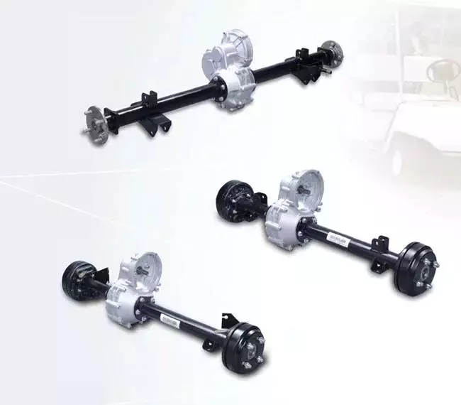
Vehicles with two axles
There are many different types of vehicles, but most are characterized by having two axles. Two axles are common in SUVs, trucks, and other vehicles that are meant to be off-road or for light hauling. Vehicles with two axles also include light-duty cargo vans and passenger cars.
There are many different kinds of two-axle vehicles, ranging from bicycles to motorcycles. In the United States, the most common kind of two-axle vehicles are pickup trucks, SUVs, and sedans. Three-axle vehicles are also common, with the largest type being tractor-trailers. Four-axle vehicles are rare, though. Some class 8 trucks have two-axle tractors.
Two-axle vehicles typically have two axles, with one axle supporting each of the two wheels. Other types of vehicles have three or four axles. The more axles a vehicle has, the more stability it has and the more weight it can handle. Two-axle vehicles are common, but three-axle vehicles are popular in transporting large cargo. Some are even designed with raised axles.
The number of axles on a car depends on its size and purpose. A car has a front axle and a rear axle. The front axle steers the vehicle, and the rear axle powers the wheels. The number of axles in a truck is largely dependent on its size and load, and some trucks have as many as four.
The front axle and rear axle are connected by a drive shaft. The driveshaft connects to the engine, which turns the axles. The two axles transfer the power from the engine to the wheels, and they may also help drive the vehicle. Axles are essential components of a vehicle, and should be strong and durable.
Axles are also important for a vehicle’s turning radius. Heavy-duty vehicles, such as semi-trucks, have large turning radii. Because they run across the width of the vehicle, axles make it possible for the wheels to turn freely. In addition to allowing the wheels to turn, they also support the weight of the vehicle.
Typical vehicles with two axles include the Toyota Rav4 and the Ford Mustang. The Rav4 uses two axles in front and rear-wheel drive. The Ford Mustang, on the other hand, has a live rear axle. In addition, the Mustang is also two axles. A tandem axle is an arrangement of two rear axles close together. It is a popular style in large vehicles.
Vehicles with three axles
There are many different types of vehicles with three axles. Some of the most common include the dump truck, Greyhound bus, and tractor-trailer. Vehicles with three axles are generally heavier than four-axle vehicles. Vehicles with three axles have two sets of wheels – one front and one back. For example, a heavy truck will have three rear axles, a semi-trailer will have two front axles, and a tow truck will have two drive axles and two steer axles.
A vehicle’s axle count can vary. A simple method of figuring out the number of axles in a vehicle is to count the wheels. There are many ways to find out the number of axles on a vehicle. You can also look in the owner’s manual or ask a mechanic. If you’re unsure, ask someone who knows how to tell if a vehicle has three or four axles.
The design of a vehicle’s axles has several benefits. One of these benefits is its ability to disperse weight across a larger area, thereby reducing the risk of the vehicle sinking into soft ground. Dump trucks often drive to delivery sites with the third axle raised, lowering it only when it’s time to cross a soft area.
The number of axles in a vehicle is a crucial factor in determining how much power it needs to move. Different vehicles are designed to handle different terrains and have different axles to match their needs. For example, two-axle vehicles have two front axles, while three-axle vehicles have three rear axles.
A front axle is located at the front of the vehicle and helps with steering and processing road shocks. A front axle is often made of carbon steel, while a stub axle is a fixed axle that supports only one wheel. The front axle is connected to the stub axle through a kingpin.
Vehicles with three axles are generally larger than two axle vehicles. However, some two-axle vehicles can be three-axle, especially if they have a trailer. The design of a vehicle with three axles depends on what type of trailer it has. A two-axle trailer will usually have a trailer attached to it, and the rear axle will be responsible for moving power from the differential to the rear wheels.
Unlike semi-floating axles, full-floating axles are supported by two large bearings. They’re used for larger vehicles with high towing capacities. They also help with wheel alignment. A three-quarter floating axle is more complex than a semi-floating axle, and is often found in mid-size trucks.
There are also vehicles with a middle axle. Figures 2 and 3 illustrate this arrangement. The front and rear axles support most of the weight of the vehicle and the secondary axle has almost no ground weight. The secondary axle has a ground weight that is only 8.5% of the vehicle’s unloaded weight. The wheels of the vehicle remain in contact with the ground. Leaf spring 1 is coupled to the middle secondary axle.
Types of axles
There are several different types of axles, and each is different in function. Some have bearings on each end, while others don’t. These two types of axles have different strengths and weaknesses, so it’s important to know which one is right for you. The best axle for your vehicle depends on your driving needs and budget.
The most basic type of axle is the axle shaft. This is the most inexpensive kind of axle. It connects the wheel hub to the axle shaft. The axle shaft is attached to the wheel hub by bolts. The wheel axle sits in the middle of the axle shaft. The bearings and axle casing transfer the weight of the wheel to the axle. The bearings are designed to distribute the weight evenly on both sides of the axle.
Another type of axle is the reverse Czpt stub axle. It is similar to the standard Czpt stub axle, but the reverse Czpt is designed with an L-shaped spindle. The rear axles also come in different types. These depend on how they are mounted on the vehicle. There are three different types of rear axles: rigid axles, semi-floating axles, and floating axles.
A full floating axle, on the other hand, does not support the weight of the vehicle. It is attached to the wheel hub and axle housing. It is most common in trucks and heavy duty vehicles. These axles are also the most durable, but they can only handle a heavy load. If the axle shaft breaks or is damaged, the vehicle will drop.
The type of axles a vehicle has is important because it affects the turning radius. A single axle vehicle has one drive axle at the rear, while a tandem vehicle has two drives. This means that the vehicle has a larger turning radius than a single axle one. There are also a variety of designs that allow it to turn at higher speeds and with less torque.
Lastly, a dead front axle is an immovable front axle, not revolving with the wheels. It is protected by housings and is a good choice for vehicles that cannot be driven in wet conditions. They provide the driving power from the Axles to the front wheels. The Czpt type uses a kingpin, while the Lamoine type uses a yoke-type hinge.
Three quarter floating axles are a hybrid between a full and semi floating axle. In this type, the axle is attached to the hub through bearings. As a result, it eliminates the shearing stress of the axle and focuses on bending loads. These axles are cheaper than the semi-floating type, and they are used in lighter trucks.
A semi-floating axle, on the other hand, has a bearing inside its axle casing. This axle is a lightweight option that still supports all the vehicle’s weight. This axle is generally used on light-duty pickups and mid-size trucks.

editor by czh 2022-11-24


