Product Description
Benefits:
Quick refunds on orders under US $1,000
Claim now
Model Number
135-180 hp
Lead Time:
Quantity(pieces) 1 – 100 101 – 300 301 – 500 >500
Est. Time(days) 3 5 10 To be negotiated
Customization:
Customized logo(Min. Order: 500 pieces)
Customized packaging(Min. Order: 500 pieces)
More
Shipping:
Support Sea freight
Overview
Quick Details
Condition:
New
Warranty:
1.5 years, 1 Year
Applicable Industries:
Manufacturing Plant, Machinery Repair Shops, Farms, Retail
Weight (KG):
10 KG
Showroom Location:
None
Video outgoing-inspection:
Provided
Machinery Test Report:
Provided
Marketing Type:
Ordinary Product
Type:
front axle of tractor
Use:
Tractors
Place of Origin:
ZheJiang , China
Brand Name:
RN
After Warranty Service:
Spare parts
Local Service Location:
None
Size:
2150*506*380
Color:
Optional
Quality:
High-Quality
Application:
Wheel Tractor
OEM:
OEM/ODM service provided
Name:
1504.31.001
Website:
Supply Ability
Supply Ability
3000 Piece/Pieces per Month
Packaging & Delivery
Packaging Details
As customers’ needed
Port
ZheJiang
Lead Time:
Quantity(pieces) 1 – 100 101 – 300 301 – 500 >500
Est. Time(days) 3 5 10 To be negotiated
/* March 10, 2571 17:59:20 */!function(){function s(e,r){var a,o={};try{e&&e.split(“,”).forEach(function(e,t){e&&(a=e.match(/(.*?):(.*)$/))&&1
| Condition: | New |
|---|
| Customization: |
Available
| Customized Request |
|---|

What is the role of axles in electric vehicles, and how do they differ from traditional axles?
Electric vehicles (EVs) have unique requirements when it comes to their drivetrain systems, including the axles. The role of axles in EVs is similar to traditional vehicles, but there are some key differences. Here’s a detailed explanation of the role of axles in electric vehicles and how they differ from traditional axles:
Role of Axles in Electric Vehicles:
The primary role of axles in electric vehicles is to transmit torque from the electric motor(s) to the wheels, enabling vehicle propulsion. The axles connect the motor(s) to the wheels and provide support for the weight of the vehicle. Axles are responsible for transferring the rotational force generated by the electric motor(s) to the wheels, allowing the vehicle to move forward or backward.
In electric vehicles, the axles are an integral part of the drivetrain system, which typically includes an electric motor(s), power electronics, and a battery pack. The axles play a crucial role in ensuring efficient power transfer and delivering the desired performance and handling characteristics of the vehicle.
Differences from Traditional Axles:
While the fundamental role of axles in electric vehicles is the same as in traditional vehicles, there are some notable differences due to the unique characteristics of electric propulsion systems:
1. Integration with Electric Motors: In electric vehicles, the axles are often integrated with the electric motors. This means that the motor(s) and axle assembly are combined into a single unit, commonly referred to as an “electric axle” or “e-axle.” This integration helps reduce the overall size and weight of the drivetrain system and simplifies installation in the vehicle.
2. High Torque Requirements: Electric motors generate high amounts of torque from the moment they start, providing instant acceleration. As a result, axles in electric vehicles need to handle higher torque loads compared to traditional axles. They are designed to withstand the torque output of the electric motor(s) and efficiently transmit it to the wheels.
3. Regenerative Braking: Electric vehicles often utilize regenerative braking, which converts the vehicle’s kinetic energy into electrical energy and stores it in the battery. The axles in electric vehicles may incorporate systems or components that enable regenerative braking, such as sensors, controllers, and electric brake actuators.
4. Space Optimization: Electric vehicles often have different packaging requirements compared to traditional internal combustion engine vehicles. The axles in electric vehicles are designed to accommodate the space constraints and specific layout of the vehicle, considering the placement of the battery pack, electric motor(s), and other components.
5. Weight Considerations: Electric vehicles strive to optimize weight distribution to enhance efficiency and handling. Axles in electric vehicles may be designed with lightweight materials or innovative construction techniques to minimize weight while maintaining structural integrity and durability.
It’s important to note that the specific design and characteristics of axles in electric vehicles can vary depending on the vehicle manufacturer, drivetrain configuration (e.g., front-wheel drive, rear-wheel drive, all-wheel drive), and other factors. Automotive manufacturers and suppliers continually innovate and develop new axle technologies to meet the evolving demands of electric vehicle propulsion systems.

Can you provide insights into the advancements in axle technology in recent years?
In recent years, there have been significant advancements in axle technology to enhance performance, efficiency, and safety in vehicles. Here are some insights into the key advancements:
- Lightweight Materials:
- Electronic Differential:
- Advanced Axle Bearings:
- Electric Axles:
- Active Suspension Integration:
- Improved Sealing and Lubrication:
- Autonomous Vehicle Integration:
One notable advancement is the use of lightweight materials in axle construction. Manufacturers have increasingly utilized materials such as aluminum alloys and high-strength steels to reduce the weight of axles without compromising strength and durability. Lighter axles contribute to improved fuel efficiency and overall vehicle performance.
Electronic differentials, also known as eDiffs, have gained popularity in recent years. They utilize sensors, actuators, and control algorithms to monitor and distribute torque between the wheels more efficiently. Electronic differentials enhance traction, stability, and handling by actively managing torque distribution, especially in vehicles equipped with advanced stability control systems.
Axle bearings have seen advancements in design and materials to reduce friction, improve efficiency, and enhance durability. For example, the use of roller bearings or tapered roller bearings has become more prevalent, offering reduced frictional losses and improved load-carrying capacity. Some manufacturers have also introduced sealed or maintenance-free bearings to minimize maintenance requirements.
With the rise of electric vehicles (EVs) and hybrid vehicles, electric axles have emerged as a significant technological advancement. Electric axles integrate electric motors, power electronics, and gear systems into the axle assembly. They eliminate the need for traditional drivetrain components, simplify vehicle packaging, and offer benefits such as instant torque, regenerative braking, and improved energy efficiency.
Advancements in axle technology have facilitated the integration of active suspension systems into axle designs. Active suspension systems use sensors, actuators, and control algorithms to adjust the suspension characteristics in real-time, providing improved ride comfort, handling, and stability. Axles with integrated active suspension components offer more precise control over vehicle dynamics.
Axles have seen advancements in sealing and lubrication technologies to enhance durability and minimize maintenance requirements. Improved sealing systems help prevent contamination and retain lubricants, reducing the risk of premature wear or damage. Enhanced lubrication systems with better heat dissipation and reduced frictional losses contribute to improved efficiency and longevity.
The development of autonomous vehicles has spurred advancements in axle technology. Axles are being designed to accommodate the integration of sensors, actuators, and communication systems necessary for autonomous driving. These advancements enable seamless integration with advanced driver-assistance systems (ADAS) and autonomous driving features, ensuring optimal performance and safety.
It’s important to note that the specific advancements in axle technology can vary across different vehicle manufacturers and models. Furthermore, ongoing research and development efforts continue to drive further innovations in axle design, materials, and functionalities.
For the most up-to-date and detailed information on axle technology advancements, it is advisable to consult automotive manufacturers, industry publications, and reputable sources specializing in automotive technology.
Are there aftermarket axles available for upgrading performance in off-road vehicles?
Yes, there are aftermarket axles available for upgrading performance in off-road vehicles. Off-road enthusiasts often seek aftermarket axle options to enhance the durability, strength, and performance of their vehicles in rugged and demanding terrains. Here’s some information about aftermarket axles for off-road applications:
1. Upgraded Axle Materials:
Aftermarket axles are typically made from high-strength materials such as chromoly steel or forged alloys. These materials offer superior strength and durability compared to stock axles, making them better suited for off-road use where extreme loads, impacts, and torsional forces are encountered.
2. Increased Axle Shaft Diameter:
Some aftermarket axles feature larger diameter shafts compared to stock axles. This increased diameter helps improve the axle’s load-carrying capacity and resistance to bending or torsion. It can also enhance the overall durability and reliability of the axle in off-road conditions.
3. Upgraded Axle Splines:
Axles with upgraded splines are designed to handle higher torque loads. Aftermarket axles may feature larger and stronger splines, providing increased power transfer capabilities and reducing the risk of spline failure, which can occur in extreme off-road situations.
4. Locking Differentials:
Some aftermarket axle options include integrated locking differentials. Locking differentials improve off-road traction by mechanically locking both wheels on an axle together, ensuring that power is distributed evenly to both wheels. This feature can be advantageous in challenging off-road conditions where maximum traction is required.
5. Lifted Vehicle Compatibility:
Aftermarket axles are often designed to accommodate lifted vehicles. Lift kits that raise the suspension height can impact the axle’s operating angles. Aftermarket axles may offer increased articulation or modified geometry to maintain proper alignment and reduce the risk of binding or premature wear.
When considering aftermarket axles for off-road vehicles, it’s essential to choose options that are compatible with your specific vehicle make, model, and suspension setup. Working with reputable manufacturers, consulting with experienced off-road enthusiasts, or seeking advice from professional mechanics can help you select the most suitable aftermarket axle upgrades for your off-road needs.
Lastly, it’s important to keep in mind that upgrading axles alone may not be sufficient for maximizing off-road performance. Other components such as suspension, tires, differential gears, and drivetrain systems should be considered as part of a comprehensive off-road build to ensure optimal performance, reliability, and safety.


editor by CX 2023-12-27
China 4wd Agricultural Tractor Trailer Front Wheel Drive Steer Axle with Hydraulic Brakes Drums dexter axle
Use: Trailer Parts
Components: Trailer Axles
OE NO.: Recognized
Max Payload: 1.5ton
Dimension: Customized
Axles Title: Front Steer&Drive Axle
Axles Material: Steel
Axles Ability: 1.5ton
Axles Housing: Press-welding
Axles Pace ratio: Optional
Axles Output Torque: forty fiveMore Axle and Elements
Our Providers
Software
Packaging & Shipping and delivery
Certifications
Organization Details
Company Profile
We, Transmission Shaft Connector Shaft Connector Rigid Couplings For 3D Printer Shaft Rigid Coupling CZPT Equipment,as a sub-firm of CZPT Expenditure Group, is a proffessional spare parts provider to all varieties of vehicles and machinery since 1990.
Yet again,we are the leader of axle manufactor in China,and maintain long-time period cooperation with plenty of vehicle spare elements factories,we can give you a single-end buy services to total vehicle chassis spare components,
” Dependable-Quality, Resonable-Cost, Quickly-Shipping ” is our services principle, after much more than 30 a long time improvements, large-top quality BA1-0026 bearing air compressor bearing BA1-0026 Radial cylindrical roller bearing BA1-0026 we are the primary supplier to car industries & reffitting factories at home and abroard,
Welcome to go to our manufacturing unit for enterprise collectively.
FAQQ1. What’s the MOQ? Can I acquire 1 sample for tests?A: Always MOQ is 5-fifty Piece to different parts . We settle for sample or demo purchase.Q2. Can you offer Free SAMPLE?A: Sorry, our sample coverage is that you might pay for the sample and transport expense first, and we will refund it when you purchase them in mass amount not significantly less than 100-1000pcs according to MQO.Q3. What’s your supply time and shipping way?A: About 10-15days for sample shipping time (By Convey). 25-thirty times for mass production or it is dependent on your get amount (By Sea or Air as you required)This autumn. What services can we provide?A: Acknowledged Delivery Terms: FOB,CFR,CIF,EXW,CIP,DDP, 33118 taper roller bearing automobile 33118 JR bearing manufacturer DAF Acknowledged Payment Forex:USD,EUR Acknowledged Payment Sort: T/T,L/C,D/P D/A,Credit rating Card,PayPal,Cash Language Spoken:English,ChineseQ5. How to get the suitable areas for my cars, what should I do?A: Make sure you deliver your vehicle specifications in specifics, one hundred forty five 0571 5 oiles bushing,bronze graphite oilless bearing sleeve bushing manufacturing facility, five hundred SPB bronze oiles bearing it is far better to ship the areas photograph and drawing or samples for our checking.
Q6. How can we guarantee high quality?A: Often a pre-creation sample prior to mass manufacturing
Usually one hundred% take a look at to closing Inspection before shipment.
Axle Types
An axle is the central shaft of a rotating gear or wheel. Axles are either fixed to the wheels or mounted directly to the vehicle. They rotate with the wheels and can be equipped with bearings for smooth operation. Axle types include Czpt axles, Drop out axles, and Splines. Each has a unique design and function.
Spindles
The spindles on a vehicle’s axle are the main components that connect the wheels to the axle. They mount the wheels on the axle and fasten the braking system to the axle assembly. The spindles are fastened to the axle assembly with king pins and ball joints. They also fasten the wheel hub to the spindle via a castelated nut. In both applications, axle spindles are pivot points that are used to make turning motion possible.
There are three types of spindles for an axle. Typically, the spindles are bolted to the ends of a tubular axle, which is suspended by springs. The third type is a short stub axle, which uses a torsion beam to help the axle maintain a smooth ride over bumpy terrain.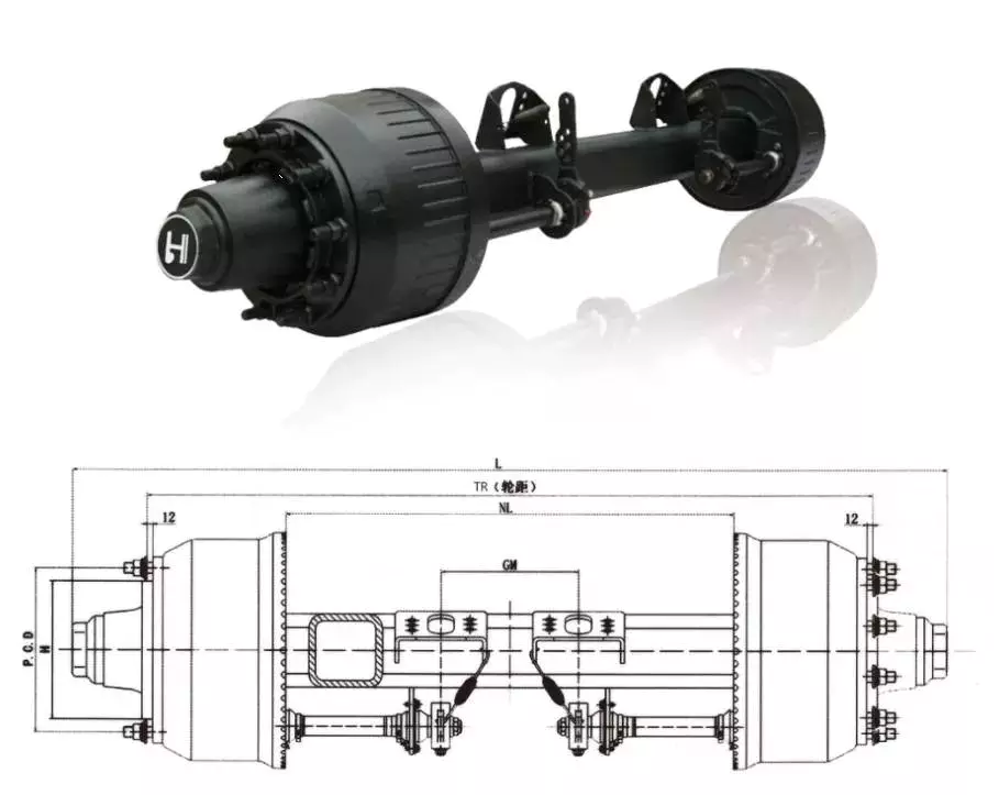
Czpt axles
Czpt axles are available in a variety of configurations. From beam-to-independent designs to single-point-to-double-point designs, there’s a Czpt axle to fit your needs. These axles are designed to provide maximum power in a small package. Czpt has a proven track record of innovation and durability.
Czpt axles are found in front-end steering vehicles and heavy-duty pickups. Some models only use the front axle. There are also Czpt axles for light-duty pickups. You can easily recognize a Czpt axle by its shape. Some online sources offer diagrams to help you identify the axle.
Among the most popular Czpt axles are the Czpt 60 and the Czpt 44. Both models are desirable in their own right. You can order Czpt axle parts from the Czpt website. These products include u joints, differential cases, and loc pins. These parts can be purchased online, and they will be delivered right to your door.
In addition to the Czpt 60 front axle, Czpt axles also feature great aftermarket support. They can be upgraded with locking differentials, limited slip differentials, and high-capacity differential covers. They also feature heat-sinks that keep the axle cool. Czpt axles are also compatible with nearly every traction aid in the market.
Czpt is a global leader in driveline products and genuine service parts. With over a century of experience manufacturing quality products, Czpt axles provide performance and reliability.
Drop out axles
Drop out axles are crucial for mounting a front wheel to a bike. If the axles are not present, the wheel will not be able to be mounted. These dropouts are made of either steel or aluminum. They are 5.8mm thick. Axles with quick release axle hubs are compatible with steel dropouts.
Axle manufacturers make different dropout axles that are compatible with different axle sizes. These axles are available in a wide range of styles. The Shimano modular dropout, for example, is available in three main axle specifications: Road, Track, and Maxle. These dropouts are also available with different axle pinions.
Drop out axles can be quick release or through. Quick release axles are lighter than thru axles. They weigh approximately 60 to 80 grams. The difference between quick release and thru axles is in the thread pitch. Quick release axles have a smaller pitch than thru axles, which allows for easier installation and removal.
Thru axles are a popular choice for mountain bikes. They prevent the front wheel from coming out while riding. They are more secure and can prevent a wheel from coming off when moving. They are usually made of a thicker rod and screw into the frame. Both types of dropouts have their advantages and disadvantages. You should choose the type that works best for your needs. This is a decision that you will have to make on your own.
CV joints
When your vehicle is in motion, the CV joints on your axle transfer torque to the wheels. Although these joints come in a wide variety of designs, they all contain a bearing assembly that allows them to move. These joints are protected by a rubber boot that is filled with grease to keep them lubricated. When they become worn, they can cause your car to shudder and vibrate while accelerating.
To avoid joint failure, it is important to keep the CV joints free of road debris. Luckily, the boots are made of durable rubber, and a good quality one can last 100,000 miles. Unfortunately, if the rubber boot is torn, dirt and moisture can leak into the joint. Therefore, it’s important to inspect the boots regularly, and replace them if necessary.
Damaged CV joints can make control of your vehicle extremely difficult. They can also cause your steering wheel to jerk when you’re accelerating, increasing the risk of an accident. A damaged CV joint can also lead to axle separation, which can cause massive damage and a serious safety risk. However, if you don’t have the funds to replace the joint, you can repair the problem by applying a sleeve.
Unlike other drive systems, CV axles can transfer torque at an angle. This is possible because of the constant velocity joints. They’re akin to the univeersal joints on tail shafts, except they work on a much larger angle. This allows the drive shaft to transfer torque to the front wheels smoothly. It also allows the axle to move up and down.
A damaged CV axle will make a characteristic clicking sound when you’re turning the vehicle. This noise is very distinctive and can only be heard when the vehicle is in motion. If you hear this noise, then the joint is worn and is in danger of failure. If this noise is loud and consistent, you’ll need to replace it.
editor by czh 2023-03-01
China Good quality China Factory Manufactuer Supply Dq1504 150HP 4WD Agricultural Wheel Farming Tractor with ISO Ce Certificate near me supplier
Product Description
China Factory manufactuer supply DQ1504 150HP 4WD Agricultural Wheel Farming Tractor with ISO CE certificate
Tractor Main Features and Advantages:
1.Equipped famous brand engine showing advanced capacity,low fuel consumption,high economic efficiency.
2. Streamlined appearance design, beautiful and generous.
3.Transmission Case adopt meshed shift and add the gearbox interlock device makes the operation more smoothly,reliable and easier.
4. Double action clutch with disc spring, perform steadily and easy to operate.
5. Fully hydraulic steering system greatly reduced driver’s work strength.
6. Wet disc brake device, reliable brake performance.
7. Separate injection of hydraulic oil, reliable to operate.
8. The lifter with force and position adjustment, with reliable lift.
9. Tractor PTO:
PTO in Double speed : 540/760r/min Optional, For high working efficiency.
PTO shaft of 6 or 8 spline Optional, adaptable for agricultural equipment of all over the world.
10. Big Chassis and Heavy-duty Rear axle for Durable Strong machine.
11. Full series light, ROPS,Sunshade/Canopy, Fan/Heater/Air-conditioned cabin are all available, for more comfortable driving environment.
Tractor Main specificaiton and Technical parameters:
| Model | DQ1504 |
| Drive type | 4×4, 4WD wheel type |
| Engine | |
| Engine brand and model | YTO brand, diesel engine Model LR6M3Z-23 |
| Type | In-line, direct injection,Water cooling, 4 stroke,6-cylinder |
| Aspiration way | Turbo |
| Engine power at rated speed | 110.3kw/150HP |
| Rated Power of PTO | 94 KW |
| Max. traction Force (KN) | 32.5 |
| Displacement(L) | 7.13 |
| Compression ratio | 18:1 |
| Rated speed (r/min) | 2300 |
| Lowest fuel consumption (g/kw.h) | ≤210 |
| Cylinder·Bore·Stroke | 6-110×125 |
| Fuel tank capacity (L) | 350 |
| Muffler Dimension (Dia.×Length) (mm) | φ600×295×140 |
| Muffler weight (kg) | 7.2 |
| Steering type | Full Hydraulic steering |
| Transmission | |
| Clutch | USA JpV brand, 13 inch dual-stage Clutch |
| PTO Speed (rpm) | 540/1000 |
| Gearshift | 16F+8R |
| Speed range (km/h) | F: 1.37-32.93 / R:2.09-30.63 |
| Driving brake | Wet, disk, hydro-static operate |
| Gearbox | 4×2×(2+1) |
| Gearbox shifting way | Joggle cover |
| Walking system | |
| Frame type | Frameless |
| Tyre size( front/rear) | 14.9-26/18.4-38 |
| Pressure( front/rear) (kPa) | 157-196/150-200 |
| Rim material | 330CL |
| Working device | |
| Lifter type | Semi-detached model |
| Max. Lifting force (KN) | 27 |
| Suspension model | Rear, three-point linkages |
| Suspension category | Category II or III |
| Adjusting control | Position control, float control |
| Hydraulic pump type | Gear pump CBN-E325L |
| Hydraulic output valve | 3 Groups |
| P.T.O. type | 1 type, rear |
| Spline no. of P.T.O. | 6( standard), 8, 21 |
| Diameter of spline | 35 |
| RPM | 540/1000 or 760/1000 |
| Technical parameter | |
| Overall Dimension (LxWxH) (mm) | 5240×2345×2995 |
| Wheel base (mm) | 2530/2657 |
| Track base-Front /R(mm) | 1650-2285 (1950 ex-work) /1620-2420 (1850 ex-work) |
| Track base adjusting way | Limited/unlimited |
| Minimum ground clearance (mm) | 520 |
| Min. operational weight (kg) | 4755 |
| Front /Rear axle weight (kg) | 2050/2705 |
| Front Ballast | 440kg (11 pcs, 40kg/pcs) |
| Rear Ballast | 520kg (2 lays each side) |
| Covering | Air-conditioning Cabin or Sunshade (Canopy) |
| Structure weight (kg) | 5400(without cabin)/5780 (with cabin) |
DQ1504 150HP 4WD Heavy duty big tractor showing:
Top-rank technical team and Advance R&D Center :
Advance Production workshop :
Strictly inspect for every set machine before Goods Delivery :
Company Honors and Certificates:
Personalized Packing and Transporting Service to meet different customers’ demand :
Perfect after-sale service for both Distributors and Private customers:
Please contact us if you have any demand for our Product :
Best price will be quoted for you as soon as receive your Requirement !
Types of Splines
There are 4 types of splines: Involute, Parallel key, helical, and ball. Learn about their characteristics. And, if you’re not sure what they are, you can always request a quotation. These splines are commonly used for building special machinery, repair jobs, and other applications. The CZPT Manufacturing Company manufactures these shafts. It is a specialty manufacturer and we welcome your business.
Involute splines
The involute spline provides a more rigid and durable structure, and is available in a variety of diameters and spline counts. Generally, steel, carbon steel, or titanium are used as raw materials. Other materials, such as carbon fiber, may be suitable. However, titanium can be difficult to produce, so some manufacturers make splines using other constituents.
When splines are used in shafts, they prevent parts from separating during operation. These features make them an ideal choice for securing mechanical assemblies. Splines with inward-curving grooves do not have sharp corners and are therefore less likely to break or separate while they are in operation. These properties help them to withstand high-speed operations, such as braking, accelerating, and reversing.
A male spline is fitted with an externally-oriented face, and a female spline is inserted through the center. The teeth of the male spline typically have chamfered tips to provide clearance with the transition area. The radii and width of the teeth of a male spline are typically larger than those of a female spline. These specifications are specified in ANSI or DIN design manuals.
The effective tooth thickness of a spline depends on the involute profile error and the lead error. Also, the spacing of the spline teeth and keyways can affect the effective tooth thickness. Involute splines in a splined shaft are designed so that at least 25 percent of the spline teeth engage during coupling, which results in a uniform distribution of load and wear on the spline.
Parallel key splines
A parallel splined shaft has a helix of equal-sized grooves around its circumference. These grooves are generally parallel or involute. Splines minimize stress concentrations in stationary joints and allow linear and rotary motion. Splines may be cut or cold-rolled. Cold-rolled splines have more strength than cut spines and are often used in applications that require high strength, accuracy, and a smooth surface.
A parallel key splined shaft features grooves and keys that are parallel to the axis of the shaft. This design is best suited for applications where load bearing is a primary concern and a smooth motion is needed. A parallel key splined shaft can be made from alloy steels, which are iron-based alloys that may also contain chromium, nickel, molybdenum, copper, or other alloying materials.
A splined shaft can be used to transmit torque and provide anti-rotation when operating as a linear guide. These shafts have square profiles that match up with grooves in a mating piece and transmit torque and rotation. They can also be easily changed in length, and are commonly used in aerospace. Its reliability and fatigue life make it an excellent choice for many applications.
The main difference between a parallel key splined shaft and a keyed shaft is that the former offers more flexibility. They lack slots, which reduce torque-transmitting capacity. Splines offer equal load distribution along the gear teeth, which translates into a longer fatigue life for the shaft. In agricultural applications, shaft life is essential. Agricultural equipment, for example, requires the ability to function at high speeds for extended periods of time.
Involute helical splines
Involute splines are a common design for splined shafts. They are the most commonly used type of splined shaft and feature equal spacing among their teeth. The teeth of this design are also shorter than those of the parallel spline shaft, reducing stress concentration. These splines can be used to transmit power to floating or permanently fixed gears, and reduce stress concentrations in the stationary joint. Involute splines are the most common type of splined shaft, and are widely used for a variety of applications in automotive, machine tools, and more.
Involute helical spline shafts are ideal for applications involving axial motion and rotation. They allow for face coupling engagement and disengagement. This design also allows for a larger diameter than a parallel spline shaft. The result is a highly efficient gearbox. Besides being durable, splines can also be used for other applications involving torque and energy transfer.
A new statistical model can be used to determine the number of teeth that engage for a given load. These splines are characterized by a tight fit at the major diameters, thereby transferring concentricity from the shaft to the female spline. A male spline has chamfered tips for clearance with the transition area. ANSI and DIN design manuals specify the different classes of fit.
The design of involute helical splines is similar to that of gears, and their ridges or teeth are matched with the corresponding grooves in a mating piece. It enables torque and rotation to be transferred to a mate piece while maintaining alignment of the 2 components. Different types of splines are used in different applications. Different splines can have different levels of tooth height.
Involute ball splines
When splines are used, they allow the shaft and hub to engage evenly over the shaft’s entire circumference. Because the teeth are evenly spaced, the load that they can transfer is uniform and their position is always the same regardless of shaft length. Whether the shaft is used to transmit torque or to transmit power, splines are a great choice. They provide maximum strength and allow for linear or rotary motion.
There are 3 basic types of splines: helical, crown, and ball. Crown splines feature equally spaced grooves. Crown splines feature involute sides and parallel sides. Helical splines use involute teeth and are often used in small diameter shafts. Ball splines contain a ball bearing inside the splined shaft to facilitate rotary motion and minimize stress concentration in stationary joints.
The 2 types of splines are classified under the ANSI classes of fit. Fillet root splines have teeth that mesh along the longitudinal axis of rotation. Flat root splines have similar teeth, but are intended to optimize strength for short-term use. Both types of splines are important for ensuring the shaft aligns properly and is not misaligned.
The friction coefficient of the hub is a complex process. When the hub is off-center, the center moves in predictable but irregular motion. Moreover, when the shaft is centered, the center may oscillate between being centered and being off-center. To compensate for this, the torque must be adequate to keep the shaft in its axis during all rotation angles. While straight-sided splines provide similar centering, they have lower misalignment load factors.
Keyed shafts
Essentially, splined shafts have teeth or ridges that fit together to transfer torque. Because splines are not as tall as involute gears, they offer uniform torque transfer. Additionally, they provide the opportunity for torque and rotational changes and improve wear resistance. In addition to their durability, splined shafts are popular in the aerospace industry and provide increased reliability and fatigue life.
Keyed shafts are available in different materials, lengths, and diameters. When used in high-power drive applications, they offer higher torque and rotational speeds. The higher torque they produce helps them deliver power to the gearbox. However, they are not as durable as splined shafts, which is why the latter is usually preferred in these applications. And while they’re more expensive, they’re equally effective when it comes to torque delivery.
Parallel keyed shafts have separate profiles and ridges and are used in applications requiring accuracy and precision. Keyed shafts with rolled splines are 35% stronger than cut splines and are used where precision is essential. These splines also have a smooth finish, which can make them a good choice for precision applications. They also work well with gears and other mechanical systems that require accurate torque transfer.
Carbon steel is another material used for splined shafts. Carbon steel is known for its malleability, and its shallow carbon content helps create reliable motion. However, if you’re looking for something more durable, consider ferrous steel. This type contains metals such as nickel, chromium, and molybdenum. And it’s important to remember that carbon steel is not the only material to consider.


China manufacturer Factory Directly Supply Dq1804 180HP 4X4 4WD Heavy Duty Big Agricultural Wheel Farm Tractor with Europe Ce Certificate near me manufacturer
Product Description
Factory directly supply DQ1804 180HP 4×4 4WD Heavy duty big Agricultural Wheel Farm Tractor with Europe CE certificate
Tractor Main Features and Advantages:
1.Equipped famous brand engine showing advanced capacity,low fuel consumption,high economic efficiency.
2. Streamlined appearance design, beautiful and generous.
3.Transmission Case adopt meshed shift and add the gearbox interlock device makes the operation more smoothly,reliable and easier.
4. Double action clutch with disc spring, perform steadily and easy to operate.
5. Fully hydraulic steering system greatly reduced driver’s work strength.
6. Wet disc brake device, reliable brake performance.
7. Separate injection of hydraulic oil, reliable to operate.
8. The lifter with force and position adjustment, with reliable lift.
9. Tractor PTO:
PTO in Double speed : 540/760r/min Optional, For high working efficiency.
PTO shaft of 6 or 8 spline Optional, adaptable for agricultural equipment of all over the world.
10. Big Chassis and Heavy-duty Rear axle for Durable Strong machine.
11. Full series light, ROPS,Sunshade/Canopy, Fan/Heater/Air-conditioned cabin are all available, for more comfortable driving environment.
DQ1804 180HP 4WD Tractor Main specificaiton and Technical parameters:
DQ1804 180HP 4WD Tractror details :
DQ1804 180HP 4WD Tractor have Sunshade( Canopy) and AC cabin for you choose:
Advance Manufacutring Line :
Strictly Inspecting and Full Testing for ensuring high quality product:
Various kind Tractor Packing and Transporting service to meet customers’ special demand:
Perfect after-sale service for both Distributors and Private customers:
Please contact us if you have any demand for our Product :
Best price will be quoted for you as soon as receive your Requirement !
How to Calculate Stiffness, Centering Force, Wear and Fatigue Failure of Spline Couplings
There are various types of spline couplings. These couplings have several important properties. These properties are: Stiffness, Involute splines, Misalignment, Wear and fatigue failure. To understand how these characteristics relate to spline couplings, read this article. It will give you the necessary knowledge to determine which type of coupling best suits your needs. Keeping in mind that spline couplings are usually spherical in shape, they are made of steel.
Involute splines
An effective side interference condition minimizes gear misalignment. When 2 splines are coupled with no spline misalignment, the maximum tensile root stress shifts to the left by 5 mm. A linear lead variation, which results from multiple connections along the length of the spline contact, increases the effective clearance or interference by a given percentage. This type of misalignment is undesirable for coupling high-speed equipment.
Involute splines are often used in gearboxes. These splines transmit high torque, and are better able to distribute load among multiple teeth throughout the coupling circumference. The involute profile and lead errors are related to the spacing between spline teeth and keyways. For coupling applications, industry practices use splines with 25 to 50-percent of spline teeth engaged. This load distribution is more uniform than that of conventional single-key couplings.
To determine the optimal tooth engagement for an involved spline coupling, Xiangzhen Xue and colleagues used a computer model to simulate the stress applied to the splines. The results from this study showed that a “permissible” Ruiz parameter should be used in coupling. By predicting the amount of wear and tear on a crowned spline, the researchers could accurately predict how much damage the components will sustain during the coupling process.
There are several ways to determine the optimal pressure angle for an involute spline. Involute splines are commonly measured using a pressure angle of 30 degrees. Similar to gears, involute splines are typically tested through a measurement over pins. This involves inserting specific-sized wires between gear teeth and measuring the distance between them. This method can tell whether the gear has a proper tooth profile.
The spline system shown in Figure 1 illustrates a vibration model. This simulation allows the user to understand how involute splines are used in coupling. The vibration model shows 4 concentrated mass blocks that represent the prime mover, the internal spline, and the load. It is important to note that the meshing deformation function represents the forces acting on these 3 components.
Stiffness of coupling
The calculation of stiffness of a spline coupling involves the measurement of its tooth engagement. In the following, we analyze the stiffness of a spline coupling with various types of teeth using 2 different methods. Direct inversion and blockwise inversion both reduce CPU time for stiffness calculation. However, they require evaluation submatrices. Here, we discuss the differences between these 2 methods.
The analytical model for spline couplings is derived in the second section. In the third section, the calculation process is explained in detail. We then validate this model against the FE method. Finally, we discuss the influence of stiffness nonlinearity on the rotor dynamics. Finally, we discuss the advantages and disadvantages of each method. We present a simple yet effective method for estimating the lateral stiffness of spline couplings.
The numerical calculation of the spline coupling is based on the semi-analytical spline load distribution model. This method involves refined contact grids and updating the compliance matrix at each iteration. Hence, it consumes significant computational time. Further, it is difficult to apply this method to the dynamic analysis of a rotor. This method has its own limitations and should be used only when the spline coupling is fully investigated.
The meshing force is the force generated by a misaligned spline coupling. It is related to the spline thickness and the transmitting torque of the rotor. The meshing force is also related to the dynamic vibration displacement. The result obtained from the meshing force analysis is given in Figures 7, 8, and 9.
The analysis presented in this paper aims to investigate the stiffness of spline couplings with a misaligned spline. Although the results of previous studies were accurate, some issues remained. For example, the misalignment of the spline may cause contact damages. The aim of this article is to investigate the problems associated with misaligned spline couplings and propose an analytical approach for estimating the contact pressure in a spline connection. We also compare our results to those obtained by pure numerical approaches.
Misalignment
To determine the centering force, the effective pressure angle must be known. Using the effective pressure angle, the centering force is calculated based on the maximum axial and radial loads and updated Dudley misalignment factors. The centering force is the maximum axial force that can be transmitted by friction. Several published misalignment factors are also included in the calculation. A new method is presented in this paper that considers the cam effect in the normal force.
In this new method, the stiffness along the spline joint can be integrated to obtain a global stiffness that is applicable to torsional vibration analysis. The stiffness of bearings can also be calculated at given levels of misalignment, allowing for accurate estimation of bearing dimensions. It is advisable to check the stiffness of bearings at all times to ensure that they are properly sized and aligned.
A misalignment in a spline coupling can result in wear or even failure. This is caused by an incorrectly aligned pitch profile. This problem is often overlooked, as the teeth are in contact throughout the involute profile. This causes the load to not be evenly distributed along the contact line. Consequently, it is important to consider the effect of misalignment on the contact force on the teeth of the spline coupling.
The centre of the male spline in Figure 2 is superposed on the female spline. The alignment meshing distances are also identical. Hence, the meshing force curves will change according to the dynamic vibration displacement. It is necessary to know the parameters of a spline coupling before implementing it. In this paper, the model for misalignment is presented for spline couplings and the related parameters.
Using a self-made spline coupling test rig, the effects of misalignment on a spline coupling are studied. In contrast to the typical spline coupling, misalignment in a spline coupling causes fretting wear at a specific position on the tooth surface. This is a leading cause of failure in these types of couplings.
Wear and fatigue failure
The failure of a spline coupling due to wear and fatigue is determined by the first occurrence of tooth wear and shaft misalignment. Standard design methods do not account for wear damage and assess the fatigue life with big approximations. Experimental investigations have been conducted to assess wear and fatigue damage in spline couplings. The tests were conducted on a dedicated test rig and special device connected to a standard fatigue machine. The working parameters such as torque, misalignment angle, and axial distance have been varied in order to measure fatigue damage. Over dimensioning has also been assessed.
During fatigue and wear, mechanical sliding takes place between the external and internal splines and results in catastrophic failure. The lack of literature on the wear and fatigue of spline couplings in aero-engines may be due to the lack of data on the coupling’s application. Wear and fatigue failure in splines depends on a number of factors, including the material pair, geometry, and lubrication conditions.
The analysis of spline couplings shows that over-dimensioning is common and leads to different damages in the system. Some of the major damages are wear, fretting, corrosion, and teeth fatigue. Noise problems have also been observed in industrial settings. However, it is difficult to evaluate the contact behavior of spline couplings, and numerical simulations are often hampered by the use of specific codes and the boundary element method.
The failure of a spline gear coupling was caused by fatigue, and the fracture initiated at the bottom corner radius of the keyway. The keyway and splines had been overloaded beyond their yield strength, and significant yielding was observed in the spline gear teeth. A fracture ring of non-standard alloy steel exhibited a sharp corner radius, which was a significant stress raiser.
Several components were studied to determine their life span. These components include the spline shaft, the sealing bolt, and the graphite ring. Each of these components has its own set of design parameters. However, there are similarities in the distributions of these components. Wear and fatigue failure of spline couplings can be attributed to a combination of the 3 factors. A failure mode is often defined as a non-linear distribution of stresses and strains.
China high quality Turkmenistan Hot Selling Dq854 85HP 4X4 4WD Agricultural Wheel Farm Tractor with Europe Ce Certificate with Free Design Custom
Product Description
Turkmenistan hot selling DQ854 85HP 4×4 4WD Agricultural wheel Farm Tractor with Europe CE certificate
Tractor Main Features and Advantages:
1.Equipped famous brand engine showing advanced capacity,low fuel consumption,high economic efficiency.
2. Streamlined appearance design, beautiful and generous.
3.Transmission Case adopt meshed shift and add the gearbox interlock device makes the operation more smoothly,reliable and easier.
4. Double action clutch with disc spring, perform steadily and easy to operate.
5. Fully hydraulic steering system greatly reduced driver’s work strength.
6. Wet disc brake device, reliable brake performance.
7. Separate injection of hydraulic oil, reliable to operate.
8. The lifter with force and position adjustment, with reliable lift.
9. Tractor PTO:
PTO in Double speed : 540/760r/min Optional, For high working efficiency.
PTO shaft of 6 or 8 spline Optional, adaptable for agricultural equipment of all over the world.
10. Big Chassis and Heavy-duty Rear axle for Durable Strong machine.
11. Full series light, ROPS,Sunshade/Canopy, Fan/Heater/Air-conditioned cabin are all available, for more comfortable driving environment.
Tractor Main specificaiton and Technical parameters:
| Tractor Model | DQ854 | ||
| Drive type | 4WD | ||
| Engine | |||
| Engine model | YTO or CZPT brand, 4 cylinder diesel engine | ||
| Capacity of fuel tank(L) | 150 | ||
| Engine power(kw/hp) | 62.5kw/85HP | ||
| PTO power at rated speed (kw) | 53 | ||
| Transmission | |||
| Clutch | Dry,dual-stage type | ||
| PTO Speed(rpm) | 540/1000 or 760/1000 | ||
| Gearshift | 8F+4R(common) /16F+8R(optional)/8F+8R(optional) | ||
| Hydraulic system | |||
| Hydraulic output valve | 2-Group (optional) | ||
| Three point linkage | |||
| Category of 3-point link | Category II | ||
| Lifting force (at point of 610mm)KN | >16 | ||
| Technical parameter | |||
| Dimension LxWxH (mm) | 4593x2050x2810 | ||
| Wheel base(mm) | 2195 | ||
| Track base(mm) front wheel | 1610 | ||
| Track base(mm) rear wheel | 1620-2571(usual 1620) | ||
| The smallest clearance(mm) | 379 | ||
| Front tyre | 11.2-24 | ||
| Rear tyre | 16.9-34(common) / 18.4-30(optional) | ||
| Optional Configurations | |||
| Common cabin with Fan; Heater cabin; AC cabin; ROPS; Canopy (Sunshade); 8F+8R shuttle gearshift, 16F+4R creeper gearshift, 2-Group Hydraulic output valve; Front ballast;Rear ballast; Paddy tire, 18.4-30 big rear tire, Air brake, Swing draw bar | |||
| Loading Quantity/40HC | 3 Sets in Nude packing for CBU shipping | ||
DQ854 85HP 4WD Tractor details :
DQ854 85HP4WD Tractor have different configurations for you choose:
Advance Manufacutring Line:
Strictly Inspecting and Full Testing for ensuring high quality product:
Tractor Packing, Loading container and Delivering goods to Customers :
Please contact us if you have any demand for our product :
Best price will be quoted for you as soon as receive your Requirement
The Functions of Splined Shaft Bearings
Splined shafts are the most common types of bearings for machine tools. They are made of a wide variety of materials, including metals and non-metals such as Delrin and nylon. They are often fabricated to reduce deflection. The tooth profile will become deformed with time, as the shaft is used over a long period of time. Splined shafts are available in a huge range of materials and lengths.
Functions
Splined shafts are used in a variety of applications and industries. They are an effective anti-rotational device, as well as a reliable means of transmitting torque. Other types of shafts are available, including key shafts, but splines are the most convenient for transmitting torque. The following article discusses the functions of splines and why they are a superior choice. Listed below are a few examples of applications and industries in which splines are used.
Splined shafts can be of several styles, depending on the application and mechanical system in question. The differences between splined shaft styles include the design of teeth, overall strength, transfer of rotational concentricity, sliding ability, and misalignment tolerance. Listed below are a few examples of splines, as well as some of their benefits. The difference between these styles is not mutually exclusive; instead, each style has a distinct set of pros and cons.
A splined shaft is a cylindrical shaft with teeth or ridges that correspond to a specific angular position. This allows a shaft to transfer torque while maintaining angular correspondence between tracks. A splined shaft is defined as a cylindrical member with several grooves cut into its circumference. These grooves are equally spaced around the shaft and form a series of projecting keys. These features give the shaft a rounded appearance and allow it to fit perfectly into a grooved cylindrical member.
While the most common applications of splines are for shortening or extending shafts, they can also be used to secure mechanical assemblies. An “involute spline” spline has a groove that is wider than its counterparts. The result is that a splined shaft will resist separation during operation. They are an ideal choice for applications where deflection is an issue.
A spline shaft’s radial torsion load distribution is equally distributed, unless a bevel gear is used. The radial torsion load is evenly distributed and will not exert significant load concentration. If the spline couplings are not aligned correctly, the spline connection can fail quickly, causing significant fretting fatigue and wear. A couple of papers discuss this issue in more detail.
Types
There are many different types of splined shafts. Each type features an evenly spaced helix of grooves on its outer surface. These grooves are either parallel or involute. Their shape allows them to be paired with gears and interchange rotary and linear motion. Splines are often cold-rolled or cut. The latter has increased strength compared to cut spines. These types of shafts are commonly used in applications requiring high strength, accuracy, and smoothness.
Another difference between internal and external splined shafts lies in the manufacturing process. The former is made of wood, while the latter is made of steel or a metal alloy. The process of manufacturing splined shafts involves cutting furrows into the surface of the material. Both processes are expensive and require expert skill. The main advantage of splined shafts is their adaptability to a wide range of applications.
In general, splined shafts are used in machinery where the rotation is transferred to an internal splined member. This member can be a gear or some other rotary device. These types of shafts are often packaged together as a hub assembly. Cleaning and lubricating are essential to the life of these components. If you’re using them on a daily basis, you’ll want to make sure to regularly inspect them.
Crowned splines are usually involute. The teeth of these splines form a spiral pattern. They are used for smaller diameter shafts because they add strength. Involute splines are also used on instrument drives and valve shafts. Serration standards are found in the SAE. Both kinds of splines can also contain a ball bearing for high torque. The difference between the 2 types of splines is the number of teeth on the shaft.
Internal splines have many advantages over external ones. For example, an internal spline shaft can be made using a grinding wheel instead of a CNC machine. It also uses a more accurate and economical process. Furthermore, it allows for a shorter manufacturing cycle, which is essential when splining high-speed machines. In addition, it stabilizes the relative phase between the spline and thread.
Manufacturing methods
There are several methods used to fabricate a splined shaft. Key and splined shafts are constructed from 2 separate parts that are shaped in a synchronized manner to transfer torque uniformly. Hot rolling is 1 method, while cold rolling utilizes low temperatures to form metal. Both methods enhance mechanical properties, surface finishes, and precision. The advantage of cold rolling is its cost-effectiveness.
Cold forming is 1 method, as well as machining and assembling. Cold forming is a unique process that allows the spline to be shaped to the desired shape. The resulting shape provides maximum contact area and torsional strength. Standard splines are available in standard sizes, but custom lengths can also be ordered. CZPT offers various auxiliary equipment, such as mating sleeves and flanged bushings.
Cold forging is another method. This method produces long splined shafts that are used in automobile propellers. After the spline portion is cut out, it is worked on in a hobbing machine. Work hardening enhances the root strength of the splined portion. It can be used for bearings, gears, and other mechanical components. Listed below are the manufacturing methods for splined shafts.
Parallel splines are the simplest of the splined shaft manufacturing methods. Parallel splines are usually welded to shafts, while involute splines are made of metal or non-metals. Splines are available in a wide variety of lengths and materials. The process is usually accompanied by a process called milling. The workpiece rotates to produce the serrated surface.
Splines are internal or external grooves in a splined shaft. They work in combination with keyways to transfer torque. Male and female splines are used in gears. Female and male splines correspond to 1 another to ensure proper angular correspondence. Involute splines have more surface area and thus are stronger than external splines. Moreover, they help the shaft fit into a grooved cylindrical member without misalignment.
A variety of other methods of manufacturing a splined shaft can be used to produce a splined shaft. Spline shafts can be produced using broaching and shaping, 2 precision machining methods. Broaching uses a metal tool with successively larger teeth to remove metal and create ridges and holes in the surface of a material. However, this process is expensive and requires special expertise.
Applications
The splined shaft is a mechanical component with a helix-like shape formed by the equal spacing of grooves in a circular ring. The splines can either have parallel or involute sides. The splines minimize stress concentration in stationary joints and can be used in both rotary and linear motion. In some cases, splines are rolled rather than cut. The latter is more durable than cut splines and is often used in applications requiring high strength, accuracy, and smooth finish.
Splined shafts are commonly made of carbon steel. This alloy steel has a low carbon content, making it easy to work with. Carbon steel is a great choice for splines because it is malleable. Generally, high-quality carbon steel provides a consistent motion. Steel alloys are also available that contain nickel, chromium, copper, and other metals. If you’re unsure of the right material for your application, you can consult a spline chart.
Splines are a versatile mechanical component. They are easy to cut and fit. Splines can be internal or external, with teeth positioned at equal intervals on both sides of the shaft. This allows the shaft to engage with the hub around the entire circumference of the hub. It also increases load capacity by creating a constant multiple-tooth point of contact with the hub. For this reason, they’re used extensively in rotary and linear motion.
Splined shafts are used in a wide variety of industries. CZPT Inc. offers custom and standard splined shafts for a variety of applications. When choosing a splined shaft for a specific application, consider the surrounding mated components, torque requirements, and size requirements. These 3 factors will make it the ideal choice for your rotary equipment. And you’ll be pleased with the end result!
There are many types of splines and their applications are endless. They transfer torque and angular misalignment between parts, and they also enable the axial rotation of assembled components. Therefore, splines are an essential component of machinery and are used in a wide range of applications. This type of shaft can be found in various types of machines, from household appliances to industrial machinery. So, the next time you’re looking for a splined shaft, make sure you look for a splined one.
China Hot selling High Quality Dq1304 130HP 4WD Heavy Duty Big Chassis Agriculture Wheeled Farm Tractor for Sale near me shop
Product Description
High Quality Dq1304 130HP 4WD Heavy Duty Big chassis Agriculture Wheeled Farm Tractor for Sale
Tractor Main Features and Advantages:
1.Equipped famous brand engine showing advanced capacity,low fuel consumption,high economic efficiency.
2. Streamlined appearance design, beautiful and generous.
3.Transmission Case adopt meshed shift and add the gearbox interlock device makes the operation more smoothly,reliable and easier.
4. Double action clutch with disc spring, perform steadily and easy to operate.
5. Fully hydraulic steering system greatly reduced driver’s work strength.
6. Wet disc brake device, reliable brake performance.
7. Separate injection of hydraulic oil, reliable to operate.
8. The lifter with force and position adjustment, with reliable lift.
9. Tractor PTO:
PTO in Double speed : 540/760r/min Optional, For high working efficiency.
PTO shaft of 6 or 8 spline Optional, adaptable for agricultural equipment of all over the world.
10. Big Chassis and Heavy-duty Rear axle for Durable Strong machine.
11. Full series light, ROPS,Sunshade/Canopy, Fan/Heater/Air-conditioned cabin are all available, for more comfortable driving environment.
Tractor Main specificaiton and Technical parameters:
| Model | DQ1304 |
| Drive type | 4×4, 4WD wheel type |
| Engine | |
| Engine brand and model | YTO brand, diesel engine Model LR6M5-22 |
| Type | In-line, direct injection,Water cooling, 4 stroke,6-cylinder |
| Engine power at rated speed | 95.6kw/130HP |
| Rated Power of PTO | 82 KW |
| Max. traction Force (KN) | 32.5 |
| Displacement(L) | 7.13 |
| Compression ratio | 18:1 |
| Rated speed (r/min) | 2200 |
| Lowest fuel consumption (g/kw.h) | ≤210 |
| Cylinder·Bore·Stroke | 6-110×125 |
| Fuel tank capacity (L) | 350 |
| Muffler Dimension (Dia.×Length) (mm) | φ600×295×140 |
| Muffler weight (kg) | 7.2 |
| Steering type | Full Hydraulic steering |
| Transmission | |
| Clutch | USA JpV brand, 13 inch dual-stage Clutch |
| PTO Speed (rpm) | 540/1000 |
| Gearshift | 16F+8R |
| Speed range (km/h) | F: 1.37-32.93 / R:2.09-30.63 |
| Driving brake | Wet, disk, hydro-static operate |
| Gearbox | 4×2×(2+1) |
| Gearbox shifting way | Joggle cover |
| Walking system | |
| Frame type | Frameless |
| Tyre size( front/rear) | 14.9-26/18.4-38 |
| Pressure( front/rear) (kPa) | 157-196/150-200 |
| Rim material | 330CL |
| Working device | |
| Lifter type | Semi-detached model |
| Max. Lifting force (KN) | 27 |
| Suspension model | Rear, three-point linkages |
| Suspension category | Category II |
| Adjusting control | Position control, float control |
| Hydraulic pump type | Gear pump CBN-E325L |
| Hydraulic output valve | 3 Groups |
| P.T.O. type | 1 type, rear |
| Spline no. of P.T.O. | 6( standard), 8, 21 |
| Diameter of spline | 35 |
| RPM | 540/1000 or 760/1000 |
| Technical parameter | |
| Overall Dimension (LxWxH) (mm) | 5240×2345×2995 |
| Wheel base (mm) | 2530/2657 |
| Track base-Front /R(mm) | 1650-2285 (1950 ex-work) /1620-2420 (1850 ex-work) |
| Track base adjusting way | Limited/unlimited |
| Minimum ground clearance (mm) | 520 |
| Min. operational weight (kg) | 4755 |
| Front /Rear axle weight (kg) | 2050/2705 |
| Front Ballast | 440kg (11 pcs, 40kg/pcs) |
| Rear Ballast | 520kg (2 lays each side) |
| Covering | Air-conditioning Cabin or Sunshade (Canopy) |
| Structure weight (kg) | 5400(without cabin)/5780 (with cabin) |
DQ1304 130HP 4WD Heavy duty tractor showing:
Top-rank technical team and Advance R&D Center :
Advance Production workshop :
Strictly inspect for every set machine before Goods Delivery :
Company Honors and Certificates:
Personalized Packing and Transporting Service to meet different customers’ demand :
Perfect after-sale service for both Distributors and Private customers:
Please contact us if you have any demand for our Product :
Best price will be quoted for you as soon as receive your Requirement !
The Benefits of Spline Couplings for Disc Brake Mounting Interfaces
Spline couplings are commonly used for securing disc brake mounting interfaces. Spline couplings are often used in high-performance vehicles, aeronautics, and many other applications. However, the mechanical benefits of splines are not immediately obvious. Listed below are the benefits of spline couplings. We’ll discuss what these advantages mean for you. Read on to discover how these couplings work.
Disc brake mounting interfaces are splined
There are 2 common disc brake mounting interfaces – splined and six-bolt. Splined rotors fit on splined hubs; six-bolt rotors will need an adapter to fit on six-bolt hubs. The six-bolt method is easier to maintain and may be preferred by many cyclists. If you’re thinking of installing a disc brake system, it is important to know how to choose the right splined and center lock interfaces.
Aerospace applications
The splines used for spline coupling in aircraft are highly complex. While some previous researches have addressed the design of splines, few publications have tackled the problem of misaligned spline coupling. Nevertheless, the accurate results we obtained were obtained using dedicated simulation tools, which are not commercially available. Nevertheless, such tools can provide a useful reference for our approach. It would be beneficial if designers could use simple tools for evaluating contact pressure peaks. Our analytical approach makes it possible to find answers to such questions.
The design of a spline coupling for aerospace applications must be accurate to minimize weight and prevent failure mechanisms. In addition to weight reduction, it is necessary to minimize fretting fatigue. The pressure distribution on the spline coupling teeth is a significant factor in determining its fretting fatigue. Therefore, we use analytical and experimental methods to examine the contact pressure distribution in the axial direction of spline couplings.
The teeth of a spline coupling can be categorized by the type of engagement they provide. This study investigates the position of resultant contact forces in the teeth of a spline coupling when applied to pitch diameter. Using FEM models, numerical results are generated for nominal and parallel offset misalignments. The axial tooth profile determines the behavior of the coupling component and its ability to resist wear. Angular misalignment is also a concern, causing misalignment.
In order to assess wear damage of a spline coupling, we must take into consideration the impact of fretting on the components. This wear is caused by relative motion between the teeth that engage them. The misalignment may be caused by vibrations, cyclical tooth deflection, or angular misalignment. The result of this analysis may help designers improve their spline coupling designs and develop improved performance.
CZPT polyimide, an abrasion-resistant polymer, is a popular choice for high-temperature spline couplings. This material reduces friction and wear, provides a low friction surface, and has a low wear rate. Furthermore, it offers up to 50 times the life of metal on metal spline connections. For these reasons, it is important to choose the right material for your spline coupling.
High-performance vehicles
A spline coupler is a device used to connect splined shafts. A typical spline coupler resembles a short pipe with splines on either end. There are 2 basic types of spline coupling: single and dual spline. One type attaches to a drive shaft, while the other attaches to the gearbox. While spline couplings are typically used in racing, they’re also used for performance problems.
The key challenge in spline couplings is to determine the optimal dimension of spline joints. This is difficult because no commercial codes allow the simulation of misaligned joints, which can destroy components. This article presents analytical approaches to estimating contact pressures in spline connections. The results are comparable with numerical approaches but require special codes to accurately model the coupling operation. This research highlights several important issues and aims to make the application of spline couplings in high-performance vehicles easier.
The stiffness of spline assemblies can be calculated using tooth-like structures. Such splines can be incorporated into the spline joint to produce global stiffness for torsional vibration analysis. Bearing reactions are calculated for a certain level of misalignment. This information can be used to design bearing dimensions and correct misalignment. There are 3 types of spline couplings.
Major diameter fit splines are made with tightly controlled outside diameters. This close fit provides concentricity transfer from the male to the female spline. The teeth of the male spline usually have chamfered tips and clearance with fillet radii. These splines are often manufactured from billet steel or aluminum. These materials are renowned for their strength and uniform grain created by the forging process. ANSI and DIN design manuals define classes of fit.
Disc brake mounting interfaces
A spline coupling for disc brake mounting interfaces is a type of hub-to-brake-disc mount. It is a highly durable coupling mechanism that reduces heat transfer from the disc to the axle hub. The mounting arrangement also isolates the axle hub from direct contact with the disc. It is also designed to minimize the amount of vehicle downtime and maintenance required to maintain proper alignment.
Disc brakes typically have substantial metal-to-metal contact with axle hub splines. The discs are held in place on the hub by intermediate inserts. This metal-to-metal contact also aids in the transfer of brake heat from the brake disc to the axle hub. Spline coupling for disc brake mounting interfaces comprises a mounting ring that is either a threaded or non-threaded spline.
During drag brake experiments, perforated friction blocks filled with various additive materials are introduced. The materials included include Cu-based powder metallurgy material, a composite material, and a Mn-Cu damping alloy. The filling material affects the braking interface’s wear behavior and friction-induced vibration characteristics. Different filling materials produce different types of wear debris and have different wear evolutions. They also differ in their surface morphology.
Disc brake couplings are usually made of 2 different types. The plain and HD versions are interchangeable. The plain version is the simplest to install, while the HD version has multiple components. The two-piece couplings are often installed at the same time, but with different mounting interfaces. You should make sure to purchase the appropriate coupling for your vehicle. These interfaces are a vital component of your vehicle and must be installed correctly for proper operation.
Disc brakes use disc-to-hub elements that help locate the forces and displace them to the rim. These elements are typically made of stainless steel, which increases the cost of manufacturing the disc brake mounting interface. Despite their benefits, however, the high braking force loads they endure are hard on the materials. Moreover, excessive heat transferred to the intermediate elements can adversely affect the fatigue life and long-term strength of the brake system.
China Standard High Quality Enfly Brand 80HP 85HP 90HP 95HP 100HP 110HP 4X4 4WD Big Agriculture Wheel Farming Tractor with Td Bype Big Chassis for Sale with Hot selling
Product Description
High quality Enfly brand 80HP 85HP 90HP 95HP 100HP 110HP 4×4 4WD Big Agriculture wheel Farming Tractor with TD bype big Chassis for sale
Tractor Main Features and Advantages:
1.Equipped famous brand engine showing advanced capacity,low fuel consumption,high economic efficiency.
2. Streamlined appearance design, beautiful and generous.
3.Transmission Case adopt meshed shift and add the gearbox interlock device makes the operation more smoothly,reliable and easier.
4. Double action clutch with disc spring, perform steadily and easy to operate.
5. Fully hydraulic steering system greatly reduced driver’s work strength.
6. Wet disc brake device, reliable brake performance.
7. Separate injection of hydraulic oil, reliable to operate.
8. The lifter with force and position adjustment, with reliable lift.
9. Tractor PTO:
PTO in Double speed : 540/760r/min Optional, For high working efficiency.
PTO shaft of 6 or 8 spline Optional, adaptable for agricultural equipment of all over the world.
10. Big Chassis and Heavy-duty Rear axle for Durable Strong machine.
11. Full series light, ROPS,Sunshade/Canopy, Fan/Heater/Air-conditioned cabin are all available, for more comfortable driving environment.
Tractor Main specificaiton and Technical parameters:
| Tractor Model | DQ1004 |
| Drive type | 4×4, 4WD |
| Engine | |
| Engine type | YTO or CZPT brand, 4 or 6 cylinder diesel engine |
| Capacity of fuel tank(L) | 150 |
| Rated speed (r/min) | 2300 |
| Engine power at rated speed(kw/hp) | 73.5kw/100HP |
| Transmission | |
| Clutch | Dry,Dual-stage type |
| PTO Speed (rpm) | 540/1000 or 760/1000 |
| Gear shift | 8F+4R/16F+8R(optional)/8F+8R(optional) |
| Hydraulic system | |
| Hydraulic output valve | 2-Group (optional) |
| Three point linkage | |
| Category of 3-point link | Category II |
| Lifting force @ point of 610mm) KN | >16 |
| Technical parameter | |
| Dimension (LxWxH) (mm) | 4593x2050x2810 |
| Wheel base(mm) | 2195 |
| Track base(mm) front wheel | 1610 |
| Track base(mm) rear wheel | 1620-2571 (usual 1620) |
| The smallest clearance(mm) | 379 |
| Front tyre | 11.2-24 |
| Rear tyre | 16.9-34(common)/18.4-30(optional) |
| Optional Configurations | |
| Common cabin with Fan; Heater cabin; AC cabin; ROPS; Canopy (Sunshade); 8F+8R shuttle gearshift, 16F+4R creeper gearshift, 2-Group Hydraulic output valve; Front ballast, Rear ballast; Paddy tire, 7.5-16 front tire, 18.4-30 big rear tire, 6 cylinder diesel engine, Heavy-duty rear, Air brake, Swing draw bar | |
| Loading Quantity/40HC | 3 Sets in Nude packing for CBU shipping |
Tractror details showing:
Tractor have different configurations for you choose:
Advance Manufacutring Line :
Strictly Inspecting and Full Testing for ensuring high quality product:
Tractor Packing, Loading container and Delivering goods to Customers :
Best price will be quoted for you as soon as receive your Requirement !
Types of Splines
There are 4 types of splines: Involute, Parallel key, helical, and ball. Learn about their characteristics. And, if you’re not sure what they are, you can always request a quotation. These splines are commonly used for building special machinery, repair jobs, and other applications. The CZPT Manufacturing Company manufactures these shafts. It is a specialty manufacturer and we welcome your business.
Involute splines
The involute spline provides a more rigid and durable structure, and is available in a variety of diameters and spline counts. Generally, steel, carbon steel, or titanium are used as raw materials. Other materials, such as carbon fiber, may be suitable. However, titanium can be difficult to produce, so some manufacturers make splines using other constituents.
When splines are used in shafts, they prevent parts from separating during operation. These features make them an ideal choice for securing mechanical assemblies. Splines with inward-curving grooves do not have sharp corners and are therefore less likely to break or separate while they are in operation. These properties help them to withstand high-speed operations, such as braking, accelerating, and reversing.
A male spline is fitted with an externally-oriented face, and a female spline is inserted through the center. The teeth of the male spline typically have chamfered tips to provide clearance with the transition area. The radii and width of the teeth of a male spline are typically larger than those of a female spline. These specifications are specified in ANSI or DIN design manuals.
The effective tooth thickness of a spline depends on the involute profile error and the lead error. Also, the spacing of the spline teeth and keyways can affect the effective tooth thickness. Involute splines in a splined shaft are designed so that at least 25 percent of the spline teeth engage during coupling, which results in a uniform distribution of load and wear on the spline.
Parallel key splines
A parallel splined shaft has a helix of equal-sized grooves around its circumference. These grooves are generally parallel or involute. Splines minimize stress concentrations in stationary joints and allow linear and rotary motion. Splines may be cut or cold-rolled. Cold-rolled splines have more strength than cut spines and are often used in applications that require high strength, accuracy, and a smooth surface.
A parallel key splined shaft features grooves and keys that are parallel to the axis of the shaft. This design is best suited for applications where load bearing is a primary concern and a smooth motion is needed. A parallel key splined shaft can be made from alloy steels, which are iron-based alloys that may also contain chromium, nickel, molybdenum, copper, or other alloying materials.
A splined shaft can be used to transmit torque and provide anti-rotation when operating as a linear guide. These shafts have square profiles that match up with grooves in a mating piece and transmit torque and rotation. They can also be easily changed in length, and are commonly used in aerospace. Its reliability and fatigue life make it an excellent choice for many applications.
The main difference between a parallel key splined shaft and a keyed shaft is that the former offers more flexibility. They lack slots, which reduce torque-transmitting capacity. Splines offer equal load distribution along the gear teeth, which translates into a longer fatigue life for the shaft. In agricultural applications, shaft life is essential. Agricultural equipment, for example, requires the ability to function at high speeds for extended periods of time.
Involute helical splines
Involute splines are a common design for splined shafts. They are the most commonly used type of splined shaft and feature equal spacing among their teeth. The teeth of this design are also shorter than those of the parallel spline shaft, reducing stress concentration. These splines can be used to transmit power to floating or permanently fixed gears, and reduce stress concentrations in the stationary joint. Involute splines are the most common type of splined shaft, and are widely used for a variety of applications in automotive, machine tools, and more.
Involute helical spline shafts are ideal for applications involving axial motion and rotation. They allow for face coupling engagement and disengagement. This design also allows for a larger diameter than a parallel spline shaft. The result is a highly efficient gearbox. Besides being durable, splines can also be used for other applications involving torque and energy transfer.
A new statistical model can be used to determine the number of teeth that engage for a given load. These splines are characterized by a tight fit at the major diameters, thereby transferring concentricity from the shaft to the female spline. A male spline has chamfered tips for clearance with the transition area. ANSI and DIN design manuals specify the different classes of fit.
The design of involute helical splines is similar to that of gears, and their ridges or teeth are matched with the corresponding grooves in a mating piece. It enables torque and rotation to be transferred to a mate piece while maintaining alignment of the 2 components. Different types of splines are used in different applications. Different splines can have different levels of tooth height.
Involute ball splines
When splines are used, they allow the shaft and hub to engage evenly over the shaft’s entire circumference. Because the teeth are evenly spaced, the load that they can transfer is uniform and their position is always the same regardless of shaft length. Whether the shaft is used to transmit torque or to transmit power, splines are a great choice. They provide maximum strength and allow for linear or rotary motion.
There are 3 basic types of splines: helical, crown, and ball. Crown splines feature equally spaced grooves. Crown splines feature involute sides and parallel sides. Helical splines use involute teeth and are often used in small diameter shafts. Ball splines contain a ball bearing inside the splined shaft to facilitate rotary motion and minimize stress concentration in stationary joints.
The 2 types of splines are classified under the ANSI classes of fit. Fillet root splines have teeth that mesh along the longitudinal axis of rotation. Flat root splines have similar teeth, but are intended to optimize strength for short-term use. Both types of splines are important for ensuring the shaft aligns properly and is not misaligned.
The friction coefficient of the hub is a complex process. When the hub is off-center, the center moves in predictable but irregular motion. Moreover, when the shaft is centered, the center may oscillate between being centered and being off-center. To compensate for this, the torque must be adequate to keep the shaft in its axis during all rotation angles. While straight-sided splines provide similar centering, they have lower misalignment load factors.
Keyed shafts
Essentially, splined shafts have teeth or ridges that fit together to transfer torque. Because splines are not as tall as involute gears, they offer uniform torque transfer. Additionally, they provide the opportunity for torque and rotational changes and improve wear resistance. In addition to their durability, splined shafts are popular in the aerospace industry and provide increased reliability and fatigue life.
Keyed shafts are available in different materials, lengths, and diameters. When used in high-power drive applications, they offer higher torque and rotational speeds. The higher torque they produce helps them deliver power to the gearbox. However, they are not as durable as splined shafts, which is why the latter is usually preferred in these applications. And while they’re more expensive, they’re equally effective when it comes to torque delivery.
Parallel keyed shafts have separate profiles and ridges and are used in applications requiring accuracy and precision. Keyed shafts with rolled splines are 35% stronger than cut splines and are used where precision is essential. These splines also have a smooth finish, which can make them a good choice for precision applications. They also work well with gears and other mechanical systems that require accurate torque transfer.
Carbon steel is another material used for splined shafts. Carbon steel is known for its malleability, and its shallow carbon content helps create reliable motion. However, if you’re looking for something more durable, consider ferrous steel. This type contains metals such as nickel, chromium, and molybdenum. And it’s important to remember that carbon steel is not the only material to consider.
China high quality Chile Hot Sale Dq1104 110HP 4WD Yto or CZPT Diesel Engine Four Wheel Farm Tractor with Comfortable Cabin with Hot selling
Product Description
High quality Agricultural Equipment DQ1104 110HP 4WD Big wheel Farming tractor from Tractor factory manufacturer
Tractor Main Features and Advantages:
1.Equipped famous brand engine showing advanced capacity,low fuel consumption,high economic efficiency.
2. Streamlined appearance design, beautiful and generous.
3.Transmission Case adopt meshed shift and add the gearbox interlock device makes the operation more smoothly,reliable and easier.
4. Double action clutch with disc spring, perform steadily and easy to operate.
5. Fully hydraulic steering system greatly reduced driver’s work strength.
6. Wet disc brake device, reliable brake performance.
7. Separate injection of hydraulic oil, reliable to operate.
8. The lifter with force and position adjustment, with reliable lift.
9. Tractor PTO:
PTO in Double speed : 540/760r/min Optional, For high working efficiency.
PTO shaft of 6 or 8 spline Optional, adaptable for agricultural equipment of all over the world.
10. Big Chassis and Heavy-duty Rear axle for Durable Strong machine.
11. Full series light, ROPS,Sunshade/Canopy, Fan/Heater/Air-conditioned cabin are all available, for more comfortable driving environment.
Tractor Main specificaiton and Technical parameters:
| Tractor Model | DQ1104 |
| Drive type | 4×4 |
| Engine | |
| Engine type | YTO or CZPT brand, 4 cylinder diesel engine |
| Capacity of fuel tank(L) | 150 |
| Rated speed (r/min) | 2300 |
| Engine power at rated speed(kw/hp) | 81kw/110HP |
| Transmission | |
| Clutch | Dry,Dual-stage type |
| PTO Speed (rpm) | 540/1000 or 760/1000 |
| Gear shift | 8F+4R/16F+8R(optional)/8F+8R(optional) |
| Hydraulic system | |
| Hydraulic output valve | 2-Group (optional) |
| Three point linkage | |
| Category of 3-point link | Category II |
| Lifting force @ point of 610mm) KN | >18 |
| Technical parameter | |
| Dimension (LxWxH) (mm) | 4593x2050x2810 |
| Wheel base(mm) | 2195 |
| Track base(mm) front wheel | 1610 |
| Track base(mm) rear wheel | 1620-2571 (usual 1620) |
| The smallest clearance(mm) | 379 |
| Front tyre | 11.2-24 |
| Rear tyre | 16.9-34(common)/18.4-30(optional) |
| Optional Configurations | |
| Common cabin with Fan; Heater cabin; AC cabin; ROPS; Canopy (Sunshade); 8F+8R shuttle gearshift, 16F+4R creeper gearshift, 2-Group Hydraulic output valve; Front ballast, Rear ballast; Paddy tire, 7.5-16 front tire, 18.4-30 big rear tire, 6 cylinder diesel engine, Heavy-duty rear, Air brake, Swing draw bar | |
| Loading Quantity/40HC | 3 Sets in Nude packing for CBU shipping |
DQ1104 110HP 4WD Tractror showing :
DQ1104 110HP 4WD Tractor have different optional configurations for choose :
Advance Manufacutring Line:
Strictly Inspecting and Full Testing for ensuring high quality product:
Tractor Packing and Loading container for Delivering goods :
Various Transport modes and Delivery term to meet different customers demand :
Please contact us if you have any demand for our product :
Best price will be quoted for you as soon as receive your Requirement !
The Benefits of Spline Couplings for Disc Brake Mounting Interfaces
Spline couplings are commonly used for securing disc brake mounting interfaces. Spline couplings are often used in high-performance vehicles, aeronautics, and many other applications. However, the mechanical benefits of splines are not immediately obvious. Listed below are the benefits of spline couplings. We’ll discuss what these advantages mean for you. Read on to discover how these couplings work.
Disc brake mounting interfaces are splined
There are 2 common disc brake mounting interfaces – splined and six-bolt. Splined rotors fit on splined hubs; six-bolt rotors will need an adapter to fit on six-bolt hubs. The six-bolt method is easier to maintain and may be preferred by many cyclists. If you’re thinking of installing a disc brake system, it is important to know how to choose the right splined and center lock interfaces.
Aerospace applications
The splines used for spline coupling in aircraft are highly complex. While some previous researches have addressed the design of splines, few publications have tackled the problem of misaligned spline coupling. Nevertheless, the accurate results we obtained were obtained using dedicated simulation tools, which are not commercially available. Nevertheless, such tools can provide a useful reference for our approach. It would be beneficial if designers could use simple tools for evaluating contact pressure peaks. Our analytical approach makes it possible to find answers to such questions.
The design of a spline coupling for aerospace applications must be accurate to minimize weight and prevent failure mechanisms. In addition to weight reduction, it is necessary to minimize fretting fatigue. The pressure distribution on the spline coupling teeth is a significant factor in determining its fretting fatigue. Therefore, we use analytical and experimental methods to examine the contact pressure distribution in the axial direction of spline couplings.
The teeth of a spline coupling can be categorized by the type of engagement they provide. This study investigates the position of resultant contact forces in the teeth of a spline coupling when applied to pitch diameter. Using FEM models, numerical results are generated for nominal and parallel offset misalignments. The axial tooth profile determines the behavior of the coupling component and its ability to resist wear. Angular misalignment is also a concern, causing misalignment.
In order to assess wear damage of a spline coupling, we must take into consideration the impact of fretting on the components. This wear is caused by relative motion between the teeth that engage them. The misalignment may be caused by vibrations, cyclical tooth deflection, or angular misalignment. The result of this analysis may help designers improve their spline coupling designs and develop improved performance.
CZPT polyimide, an abrasion-resistant polymer, is a popular choice for high-temperature spline couplings. This material reduces friction and wear, provides a low friction surface, and has a low wear rate. Furthermore, it offers up to 50 times the life of metal on metal spline connections. For these reasons, it is important to choose the right material for your spline coupling.
High-performance vehicles
A spline coupler is a device used to connect splined shafts. A typical spline coupler resembles a short pipe with splines on either end. There are 2 basic types of spline coupling: single and dual spline. One type attaches to a drive shaft, while the other attaches to the gearbox. While spline couplings are typically used in racing, they’re also used for performance problems.
The key challenge in spline couplings is to determine the optimal dimension of spline joints. This is difficult because no commercial codes allow the simulation of misaligned joints, which can destroy components. This article presents analytical approaches to estimating contact pressures in spline connections. The results are comparable with numerical approaches but require special codes to accurately model the coupling operation. This research highlights several important issues and aims to make the application of spline couplings in high-performance vehicles easier.
The stiffness of spline assemblies can be calculated using tooth-like structures. Such splines can be incorporated into the spline joint to produce global stiffness for torsional vibration analysis. Bearing reactions are calculated for a certain level of misalignment. This information can be used to design bearing dimensions and correct misalignment. There are 3 types of spline couplings.
Major diameter fit splines are made with tightly controlled outside diameters. This close fit provides concentricity transfer from the male to the female spline. The teeth of the male spline usually have chamfered tips and clearance with fillet radii. These splines are often manufactured from billet steel or aluminum. These materials are renowned for their strength and uniform grain created by the forging process. ANSI and DIN design manuals define classes of fit.
Disc brake mounting interfaces
A spline coupling for disc brake mounting interfaces is a type of hub-to-brake-disc mount. It is a highly durable coupling mechanism that reduces heat transfer from the disc to the axle hub. The mounting arrangement also isolates the axle hub from direct contact with the disc. It is also designed to minimize the amount of vehicle downtime and maintenance required to maintain proper alignment.
Disc brakes typically have substantial metal-to-metal contact with axle hub splines. The discs are held in place on the hub by intermediate inserts. This metal-to-metal contact also aids in the transfer of brake heat from the brake disc to the axle hub. Spline coupling for disc brake mounting interfaces comprises a mounting ring that is either a threaded or non-threaded spline.
During drag brake experiments, perforated friction blocks filled with various additive materials are introduced. The materials included include Cu-based powder metallurgy material, a composite material, and a Mn-Cu damping alloy. The filling material affects the braking interface’s wear behavior and friction-induced vibration characteristics. Different filling materials produce different types of wear debris and have different wear evolutions. They also differ in their surface morphology.
Disc brake couplings are usually made of 2 different types. The plain and HD versions are interchangeable. The plain version is the simplest to install, while the HD version has multiple components. The two-piece couplings are often installed at the same time, but with different mounting interfaces. You should make sure to purchase the appropriate coupling for your vehicle. These interfaces are a vital component of your vehicle and must be installed correctly for proper operation.
Disc brakes use disc-to-hub elements that help locate the forces and displace them to the rim. These elements are typically made of stainless steel, which increases the cost of manufacturing the disc brake mounting interface. Despite their benefits, however, the high braking force loads they endure are hard on the materials. Moreover, excessive heat transferred to the intermediate elements can adversely affect the fatigue life and long-term strength of the brake system.
China Best Sales Czech Republic Hot Sale Dq1204 120HP 4WD Agricultural Wheel Farm Tractor with Ce Certificate with Free Design Custom
Product Description
Czech Republic hot sale DQ1204 120HP 4WD Agricultural wheel farm tractor with CE certificate
Tractor Main Features and Advantages:
1.Equipped famous brand engine showing advanced capacity,low fuel consumption,high economic efficiency.
2. Streamlined appearance design, beautiful and generous.
3.Transmission Case adopt meshed shift and add the gearbox interlock device makes the operation more smoothly,reliable and easier.
4. Double action clutch with disc spring, perform steadily and easy to operate.
5. Fully hydraulic steering system greatly reduced driver’s work strength.
6. Wet disc brake device, reliable brake performance.
7. Separate injection of hydraulic oil, reliable to operate.
8. The lifter with force and position adjustment, with reliable lift.
9. Tractor PTO:
PTO in Double speed : 540/760r/min Optional, For high working efficiency.
PTO shaft of 6 or 8 spline Optional, adaptable for agricultural equipment of all over the world.
10. Big Chassis and Heavy-duty Rear axle for Durable Strong machine.
11. Full series light, ROPS,Sunshade/Canopy, Fan/Heater/Air-conditioned cabin are all available, for more comfortable driving environment.
Tractor Main specificaiton and Technical parameters:
DQ1204 120HP 4W D Tractor details show :
DQ1204 120HP 4WD have Various Optional configurations and colors for choose:
Advance Manufacutring Line:
Strictly Inspecting and Full Testing for ensuring high quality product:
Tractor Packing and Loading container for Delivering goods :
Please contact us if you have any demand for our product :
Best price will be quoted for you as soon as receive your Requirement !
The Different Types of Splines in a Splined Shaft
A splined shaft is a machine component with internal and external splines. The splines are formed in 4 different ways: Involute, Parallel, Serrated, and Ball. You can learn more about each type of spline in this article. When choosing a splined shaft, be sure to choose the right 1 for your application. Read on to learn about the different types of splines and how they affect the shaft’s performance.
Involute splines
Involute splines in a splined shaft are used to secure and extend mechanical assemblies. They are smooth, inwardly curving grooves that resist separation during operation. A shaft with involute splines is often longer than the shaft itself. This feature allows for more axial movement. This is beneficial for many applications, especially in a gearbox.
The involute spline is a shaped spline, similar to a parallel spline. It is angled and consists of teeth that create a spiral pattern that enables linear and rotatory motion. It is distinguished from other splines by the serrations on its flanks. It also has a flat top. It is a good option for couplers and other applications where angular movement is necessary.
Involute splines are also called involute teeth because of their shape. They are flat on the top and curved on the sides. These teeth can be either internal or external. As a result, involute splines provide greater surface contact, which helps reduce stress and fatigue. Regardless of the shape, involute splines are generally easy to machine and fit.
Involute splines are a type of splines that are used in splined shafts. These splines have different names, depending on their diameters. An example set of designations is for a 32-tooth male spline, a 2,500-tooth module, and a 30 degree pressure angle. An example of a female spline, a fillet root spline, is used to describe the diameter of the splined shaft.
The effective tooth thickness of splines is dependent on the number of keyways and the type of spline. Involute splines in splined shafts should be designed to engage 25 to 50 percent of the spline teeth during the coupling. Involute splines should be able to withstand the load without cracking.
Parallel splines
Parallel splines are formed on a splined shaft by putting 1 or more teeth into another. The male spline is positioned at the center of the female spline. The teeth of the male spline are also parallel to the shaft axis, but a common misalignment causes the splines to roll and tilt. This is common in many industrial applications, and there are a number of ways to improve the performance of splines.
Typically, parallel splines are used to reduce friction in a rotating part. The splines on a splined shaft are narrower on the end face than the interior, which makes them more prone to wear. This type of spline is used in a variety of industries, such as machinery, and it also allows for greater efficiency when transmitting torque.
Involute splines on a splined shaft are the most common. They have equally spaced teeth, and are therefore less likely to crack due to fatigue. They also tend to be easy to cut and fit. However, they are not the best type of spline. It is important to understand the difference between parallel and involute splines before deciding on which spline to use.
The difference between splined and involute splines is the size of the grooves. Involute splines are generally larger than parallel splines. These types of splines provide more torque to the gear teeth and reduce stress during operation. They are also more durable and have a longer life span. And because they are used on farm machinery, they are essential in this type of application.
Serrated splines
A Serrated Splined Shaft has several advantages. This type of shaft is highly adjustable. Its large number of teeth allows large torques, and its shorter tooth width allows for greater adjustment. These features make this type of shaft an ideal choice for applications where accuracy is critical. Listed below are some of the benefits of this type of shaft. These benefits are just a few of the advantages. Learn more about this type of shaft.
The process of hobbing is inexpensive and highly accurate. It is useful for external spline shafts, but is not suitable for internal splines. This type of process forms synchronized shapes on the shaft, reducing the manufacturing cycle and stabilizing the relative phase between spline and thread. It uses a grinding wheel to shape the shaft. CZPT Manufacturing has a large inventory of Serrated Splined Shafts.
The teeth of a Serrated Splined Shaft are designed to engage with the hub over the entire circumference of the shaft. The teeth of the shaft are spaced uniformly around the spline, creating a multiple-tooth point of contact over the entire length of the shaft. The results of these analyses are usually satisfactory. But there are some limitations. To begin with, the splines of the Serrated Splined Shaft should be chosen carefully. If the application requires large-scale analysis, it may be necessary to modify the design.
The splines of the Serrated Splined Shaft are also used for other purposes. They can be used to transmit torque to another device. They also act as an anti-rotational device and function as a linear guide. Both the design and the type of splines determine the function of the Splined Shaft. In the automobile industry, they are used in vehicles, aerospace, earth-moving machinery, and many other industries.
Ball splines
The invention relates to a ball-spinned shaft. The shaft comprises a plurality of balls that are arranged in a series and are operatively coupled to a load path section. The balls are capable of rolling endlessly along the path. This invention also relates to a ball bearing. Here, a ball bearing is 1 of the many types of gears. The following discussion describes the features of a ball bearing.
A ball-splined shaft assembly comprises a shaft with at least 1 ball-spline groove and a plurality of circumferential step grooves. The shaft is held in a first holding means that extends longitudinally and is rotatably held by a second holding means. Both the shaft and the first holding means are driven relative to 1 another by a first driving means. It is possible to manufacture a ball-splined shaft in a variety of ways.
A ball-splined shaft features a nut with recirculating balls. The ball-splined nut rides in these grooves to provide linear motion while preventing rotation. A splined shaft with a nut that has recirculating balls can also provide rotary motion. A ball splined shaft also has higher load capacities than a ball bushing. For these reasons, ball splines are an excellent choice for many applications.
In this invention, a pair of ball-spinned shafts are housed in a box under a carrier device 40. Each of the 2 shafts extends along a longitudinal line of arm 50. One end of each shaft is supported rotatably by a slide block 56. The slide block also has a support arm 58 that supports the center arm 50 in a cantilever fashion.
Sector no-go gage
A no-go gauge is a tool that checks the splined shaft for oversize. It is an effective way to determine the oversize condition of a splined shaft without removing the shaft. It measures external splines and serrations. The no-go gage is available in sizes ranging from 19mm to 130mm with a 25mm profile length.
The sector no-go gage has 2 groups of diametrally opposed teeth. The space between them is manufactured to a maximum space width and the tooth thickness must be within a predetermined tolerance. This gage would be out of tolerance if the splines were measured with a pin. The dimensions of this splined shaft can be found in the respective ANSI or DIN standards.
The go-no-go gage is useful for final inspection of thread pitch diameter. It is also useful for splined shafts and threaded nuts. The thread of a screw must match the contour of the go-no-go gage head to avoid a no-go condition. There is no substitute for a quality machine. It is an essential tool for any splined shaft and fastener manufacturer.
The NO-GO gage can detect changes in tooth thickness. It can be calibrated under ISO17025 standards and has many advantages over a non-go gage. It also gives a visual reference of the thickness of a splined shaft. When the teeth match, the shaft is considered ready for installation. It is a critical process. In some cases, it is impossible to determine the precise length of the shaft spline.
The 45-degree pressure angle is most commonly used for axles and torque-delivering members. This pressure angle is the most economical in terms of tool life, but the splines will not roll neatly like a 30 degree angle. The 45-degree spline is more likely to fall off larger than the other two. Oftentimes, it will also have a crowned look. The 37.5 degree pressure angle is a compromise between the other 2 pressure angles. It is often used when the splined shaft material is harder than usual.
China factory Big Chassis Dq804 80HP 4WD Four Wheel Farm Tractor for Sale near me shop
Product Description
Big Chassis DQ804 80HP 4WD Four Wheel Farm Tractor for Sale
Tractor Main Features and Advantages:
1.Equipped famous brand engine showing advanced capacity,low fuel consumption,high economic efficiency.
2. Streamlined appearance design, beautiful and generous.
3.Transmission Case adopt meshed shift and add the gearbox interlock device makes the operation more smoothly,reliable and easier.
4. Double action clutch with disc spring, perform steadily and easy to operate.
5. Fully hydraulic steering system greatly reduced driver’s work strength.
6. Wet disc brake device, reliable brake performance.
7. Separate injection of hydraulic oil, reliable to operate.
8. The lifter with force and position adjustment, with reliable lift.
9. Tractor PTO:
PTO in Double speed : 540/760r/min Optional, For high working efficiency.
PTO shaft of 6 or 8 spline Optional, adaptable for agricultural equipment of all over the world.
10. Big Chassis and Heavy-duty Rear axle for Durable Strong machine.
11. Full series light, ROPS,Sunshade/Canopy, Fan/Heater/Air-conditioned cabin are all available, for more comfortable driving environment.
Tractor Main specificaiton and Technical parameters:
| Tractor Model | DQ804 | |
| Drive type | 4WD | |
| Engine | ||
| Engine model | YTO or CZPT brand, 4 cylinder diesel engine | |
| Capacity of fuel tank(L) | 150 | |
| Engine power(kw/hp) | 58.8kw/80HP | |
| PTO power at rated speed (kw) | 50.2 | |
| Transmission | ||
| Clutch | Dry,dual-stage type | |
| PTO Speed(rpm) | 540/1
Best price will be quoted for you as soon as receive your Requirement !
Analytical Approaches to Estimating Contact Pressures in Spline CouplingsA spline coupling is a type of mechanical connection between 2 rotating shafts. It consists of 2 parts – a coupler and a coupling. Both parts have teeth which engage and transfer loads. However, spline couplings are typically over-dimensioned, which makes them susceptible to fatigue and static behavior. Wear phenomena can also cause the coupling to fail. For this reason, proper spline coupling design is essential for achieving optimum performance. Modeling a spline couplingSpline couplings are becoming increasingly popular in the aerospace industry, but they operate in a slightly misaligned state, causing both vibrations and damage to the contact surfaces. To solve this problem, this article offers analytical approaches for estimating the contact pressures in a spline coupling. Specifically, this article compares analytical approaches with pure numerical approaches to demonstrate the benefits of an analytical approach. Creating a spline coupling model 20The spline coupling model 20 is created by a product model software program 10. The software validates the spline coupling model against a knowledge base of configuration-dependent specification constraints and relationships. This report is then input to the ANSYS stress analyzer program. It lists the spline coupling model 20’s geometric configurations and specification values for each feature. The spline coupling model 20 is automatically recreated every time the configuration or performance specifications of the spline coupling model 20 are modified. Analysing a spline coupling model 20An analysis of a spline coupling model consists of inputting its configuration and performance specifications. These specifications may be generated from another computer program. The product model software program 10 then uses its internal knowledge base of configuration dependent specification relationships and constraints to create a valid three-dimensional parametric model 20. This model contains information describing the number and types of spline teeth 32, snaps 34, and shoulder 36. Misalignment of a spline couplingA study aimed to investigate the position of the resultant contact force in a spline coupling engaging teeth under a steady torque and rotating misalignment. The study used numerical methods based on Finite Element Method (FEM) models. It produced numerical results for nominal conditions and parallel offset misalignment. The study considered 2 levels of misalignment – 0.02 mm and 0.08 mm – with different loading levels.
| |