Product Description
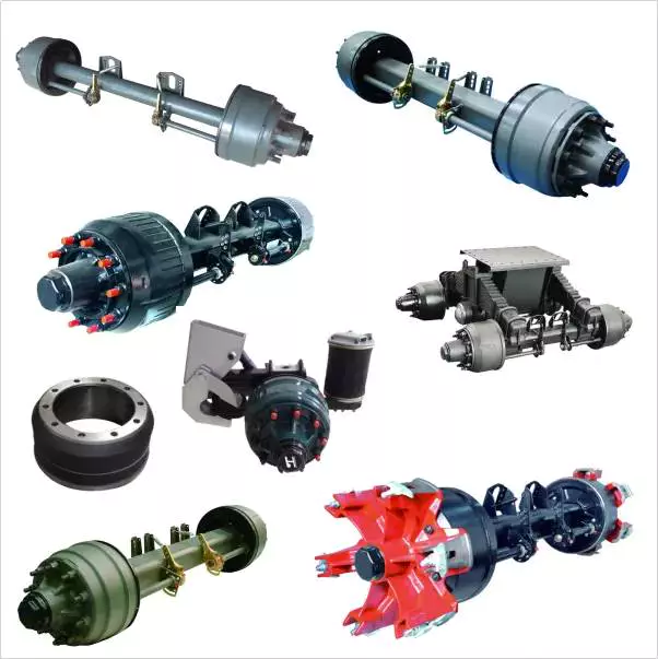
Black CZPT in Bulk Landing Gear 13ton Trailer Axle
Company introduction:
ZheJiang CZPT Co.,Ltd is 1 of the major manufacturers specializing in the production of trailer axles.
Our company has high technological background, sophisticated manufacturing technology, advances detection means, perfect quality assurance system. It is a specialized manufacturer integrating scientific research, design, production and sales.
The production of “FUSAI” trailer axles passed the national authoritative department detection. The fatigue life is up to 1,500,000 times without damage-more than 3 times above the national standard, which is in the leading domestic level, and reach or exceed the international standards. Our products are popular not only in domestic markets, but all over the world. Since the products are designed and optimized by computer, they have reasonable structure, good braking performance, high strength and rigidity, strong bearing capacity, long service life, good service, trusted by the users.
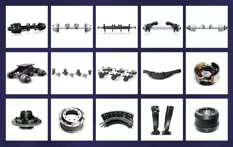
“FUSAI” brand Fuwa style trailer axle
1.CZPT spindle design which is the widely used in the industry with proven performance
2.Low-alloy machined spindles, friction welded seamlessly, and overall heat treating process
3.Axle stubs and brake hubs are all CZPT forging, ensure they are more powerful and better steady
4.Special clone-shape design on the axle-shoulders, lessening stress concentration and enhancing anti-fatigue performance
5.Unique design on axle stubs (with a precise declination angel at both ends) to minimize tire wear
6.National and industry standard compliant set components
7.National Automobile Monitor and Inspection Center certified axle shaft that undergoes over 1.2 million times of Fatigue testing and built to meet or exceed national industry standards.
Specifications:
| Axle Type | Bearings | Max. Capacity (T) |
Brake (mm) |
Track (mm) |
Center Distance Of Brake Chamber (mm) |
Axle Tube (mm) |
Stud |
PCD (mm) |
Hole Diameter (mm) |
Total Length (mm) |
Weight (kg) |
| FS- 2001 |
HM212049/10 HM218248/10 |
11 | 420*180 | 1850 | 410 | Φ127*16 | 10*M22*1.5ISO | 285.75 | 221 | 2185 | 363 |
| FS- 2002 |
HM212049/10 HM218248/10 |
11 | 420*180 | 1850 | 400 | Φ127*16 | 10*M20*1.5ISO | 335 | 281 | 2185 | 350 |
| FS- 2003 |
HM518445/10 HM518445/10 |
12 | 420*180 | 1820 | 368 | Φ127*16 127*127*16 |
10*M22*1.5ISO | 335 | 281 | 2165 | 361 |
| FS- 2004 |
HM518445/10 HM518445/10 |
12 | 420*180 | 1820 | 368 | Φ127*16 127*127*16 |
10*M20*1.5JIS | 285.75 | 221 | 2165 | 347 |
| FS- 2401 |
HM518445/10 HM518445/10 |
13 | 420*180 | 1840 | 388 | 150*150*12 | 10*M22*1.5ISO | 335 | 281 | 2185 | 363 |
| FS- 2402 |
HM518445/10 HM518445/10 |
13 | 420*180 | 1840 | 388 | 150*150*12 | 10*M20*1.5JIS | 285.75 | 221 | 2185 | 350 |
| FS- 2403 |
HM518445/10 HM518445/10 |
13 | 420*180 | 1840 | 388 | 150*150*12 | 8*M20*1.5JIS | 285 | 221 | 2185 | 365 |
| FS- 2404 |
HM518445/10 HM518445/10 |
16 | 420*220 | 1840 | 354 | 150*150*16 | 8*M22*1.5ISO | 335 | 281 | 2185 | 421 |
Attention:
1. Optional track length available.
2. Optional ABS and automatic slack adjuster available.
3. All the components are in common use of Fuwa.
4. Rights of changing product’s design and specification are reserved.
More products and information, please refer to our website: sdfhcq
ZheJiang CZPT Co.,Ltd
Sales manager: Norton Hu
/* January 22, 2571 19:08:37 */!function(){function s(e,r){var a,o={};try{e&&e.split(“,”).forEach(function(e,t){e&&(a=e.match(/(.*?):(.*)$/))&&1
| After-sales Service: | Available |
|---|---|
| Warranty: | 1 Year |
| Type: | Axle |
| Customization: |
Available
| Customized Request |
|---|
.shipping-cost-tm .tm-status-off{background: none;padding:0;color: #1470cc}
| Shipping Cost:
Estimated freight per unit. |
about shipping cost and estimated delivery time. |
|---|
| Payment Method: |
|
|---|---|
|
Initial Payment Full Payment |
| Currency: | US$ |
|---|
| Return&refunds: | You can apply for a refund up to 30 days after receipt of the products. |
|---|

What are the safety considerations when working with axles, especially during repairs?
Working with axles, especially during repairs, requires careful attention to safety to prevent accidents and injuries. Here are some important safety considerations to keep in mind when working with axles:
1. Personal Protective Equipment (PPE):
Wear appropriate personal protective equipment, including safety goggles, gloves, and steel-toed boots. PPE helps protect against potential hazards such as flying debris, sharp edges, and accidental contact with heavy components.
2. Vehicle Stability:
Ensure that the vehicle is on a stable and level surface before working on the axles. Engage the parking brake and use wheel chocks to prevent unintended vehicle movement. The stability of the vehicle is crucial to maintain a safe working environment.
3. Lifting and Support:
Use proper lifting equipment, such as hydraulic jacks or vehicle lifts, to raise the vehicle safely. Follow the manufacturer’s guidelines for lifting points and weight capacities. Once the vehicle is lifted, support it securely with jack stands or other appropriate supports to prevent it from falling or shifting during repairs.
4. Lockout/Tagout:
If the repair work involves disconnecting or removing any electrical or mechanical components that could cause the axle or wheels to move, follow lockout/tagout procedures. This involves locking and tagging out the power source, so it cannot be accidentally energized while work is being performed.
5. Proper Tools and Equipment:
Use the correct tools and equipment for the job. Using improper tools or makeshift methods can lead to accidents and damage to the axle or surrounding components. Follow the manufacturer’s instructions and recommended procedures for disassembling, repairing, and reassembling the axle.
6. Proper Torque and Tightening:
When reassembling the axle components, use a torque wrench to ensure that fasteners are tightened to the manufacturer’s specifications. Over-tightening or under-tightening can lead to component failure or damage. Follow the recommended torque values provided by the vehicle manufacturer.
7. Safe Handling of Heavy Components:
Axle components can be heavy and cumbersome. Use appropriate lifting techniques and equipment, such as hoists or lifting straps, to safely handle heavy axle parts. Avoid lifting heavy components alone whenever possible and ask for assistance when needed.
8. Proper Disposal of Fluids and Waste:
If the repair involves draining fluids from the axle, such as differential oil, ensure proper disposal according to local regulations. Use appropriate containers to collect and store fluids and dispose of them at authorized collection points.
9. Training and Experience:
Working with axles requires knowledge and experience. If you are unfamiliar with axle repairs, consider seeking assistance from a qualified mechanic or technician who has the necessary training and expertise. If you decide to perform the repairs yourself, ensure that you have the appropriate knowledge and skills to carry out the task safely.
By following these safety considerations, you can help minimize the risk of accidents, injuries, and damage when working with axles, ensuring a safe working environment for yourself and others involved in the repair process.

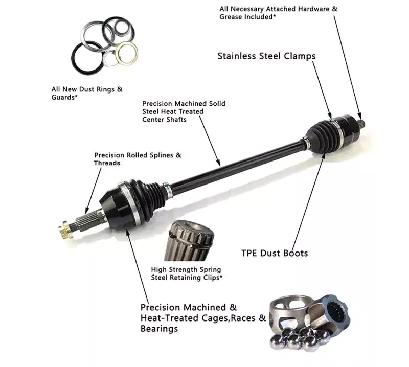
What are the symptoms of a failing CV joint, and how does it relate to the axle?
A CV (constant velocity) joint is an essential component of the axle assembly in many vehicles. When a CV joint starts to fail, it can exhibit several symptoms that indicate potential problems. Here’s a detailed explanation of the symptoms of a failing CV joint and its relationship to the axle:
Symptoms of a Failing CV Joint:
1. Clicking or popping sounds: One of the most common signs of a failing CV joint is a clicking or popping sound when making turns. This noise usually occurs during tight turns and may indicate worn-out or damaged CV joint bearings.
2. Grease leakage: A failing CV joint may leak grease, which can be seen as dark-colored grease splattered around the CV joint or on the inside of the wheel. Grease leakage is typically caused by a cracked or damaged CV joint boot, which allows the lubricating grease to escape and contaminants to enter.
3. Excessive vibration: A worn-out CV joint can cause vibrations, especially during acceleration. The vibrations may be felt in the steering wheel, floorboards, or even the entire vehicle. These vibrations can become more noticeable as the CV joint deteriorates further.
4. Difficulty in turning: As the CV joint wears out, it may become difficult to turn the vehicle, especially at low speeds or when making sharp turns. This symptom is often accompanied by a clicking or popping sound.
5. Uneven tire wear: A failing CV joint can lead to uneven tire wear. If the CV joint is damaged or worn, it can cause the axle to wobble or vibrate, resulting in uneven tire tread wear. This can be observed by visually inspecting the tires and noticing uneven patterns of wear.
Relationship to the Axle:
The CV joint is an integral part of the axle assembly. It connects the transmission to the wheels and allows smooth power delivery to the wheels while accommodating the up-and-down motion of the suspension. The axle shaft is responsible for transmitting torque from the transmission to the CV joints and ultimately to the wheels.
Axles contain one or more CV joints, depending on the vehicle’s drivetrain configuration. In front-wheel drive vehicles, each front axle typically has two CV joints, one inner and one outer. Rear-wheel drive and all-wheel drive vehicles may have CV joints on both the front and rear axles.
The CV joint consists of a joint housing, bearings, and internal ball bearings or rollers. It is protected by a rubber or thermoplastic CV joint boot, which seals in the grease and protects the joint from contaminants. When the CV joint fails, it can affect the axle’s ability to transmit power smoothly and result in the symptoms mentioned above.
Regular inspection and maintenance of the CV joint and axle assembly are crucial to identify and address any issues promptly. If any of the symptoms mentioned earlier are observed, it is recommended to have the vehicle inspected by a qualified mechanic to determine the exact cause and perform necessary repairs or replacements.

What are the signs of a worn or failing axle, and how can I troubleshoot axle issues?
Identifying the signs of a worn or failing axle is important for maintaining the safety and functionality of your vehicle. Here are some common signs to look out for and troubleshooting steps you can take to diagnose potential axle issues:
- Unusual Noises:
- Vibrations:
- Uneven Tire Wear:
- Difficulty Steering:
- Visible Damage or Leaks:
- Professional Inspection:
If you hear clunking, clicking, or grinding noises coming from the area around the wheels, it could indicate a problem with the axle. These noises may occur during acceleration, deceleration, or when turning. Troubleshoot by listening carefully to the location and timing of the noises to help pinpoint the affected axle.
A worn or failing axle can cause vibrations that can be felt through the steering wheel, floorboard, or seat. These vibrations may occur at certain speeds or during specific driving conditions. If you experience unusual vibrations, it’s important to investigate the cause, as it could be related to axle problems.
Inspect your tires for uneven wear patterns. Excessive wear on the inner or outer edges of the tires can be an indication of axle issues. Misaligned or damaged axles can cause the tires to tilt, leading to uneven tire wear. Regularly check your tires for signs of wear and take note of any abnormalities.
A worn or damaged axle can affect steering performance. If you experience difficulty in steering, such as stiffness, looseness, or a feeling of the vehicle pulling to one side, it may be due to axle problems. Pay attention to any changes in steering responsiveness and address them promptly.
Inspect the axles visually for any signs of damage or leaks. Look for cracks, bends, or visible fluid leaks around the axle boots or seals. Damaged or leaking axles can lead to lubrication loss and accelerated wear. If you notice any visible issues, it’s important to have them inspected and repaired by a qualified mechanic.
If you suspect axle issues but are unsure about the exact cause, it’s advisable to seek a professional inspection. A qualified mechanic can perform a thorough examination of the axles, suspension components, and related systems. They have the expertise and tools to diagnose axle problems accurately and recommend the appropriate repairs.
It’s important to note that troubleshooting axle issues can sometimes be challenging, as symptoms may overlap with other mechanical problems. If you’re uncertain about diagnosing or repairing axle issues on your own, it’s recommended to consult a professional mechanic. They can provide a proper diagnosis, ensure the correct repairs are performed, and help maintain the safety and performance of your vehicle.


editor by CX 2024-04-03
China Heavy trailer ratio landing gear 24T,28T wholesaler
Use: Trailer Parts
Elements: Trailer Axles
OE NO.: landing gear 24T,
Max Payload: 80T
Measurement: Normal
Product Amount: landing equipment
Fat: 90kg
Supply: 5-7 times soon after gained the payments
Color: Optional
Provider time: 7*24 several hours
OEM No: ratio landing equipment 24T,28T
Top: 840MM
Pace: Increased 3.5, Lower .forty two (mm)
Lifting Ability: 20ton 24ton 28ton
dimension: regular
Packaging Information: wooden scenario anti-ruster paper blister packing
Port: HangZhou
| Heavy trailer ratio landing gear 24T,28T | |||||||||||||||||||||||||||||||
| Sort | landing equipment | Software | landing gear | ||||||||||||||||||||||||||||
| Truck model | ratio landing equipment 24T,28T | Certification | ISO9 WhatsApp:+(18391157Email: sunnyshi <FONT color="#df
An Axle is a Simple Machine For Amplifying ForceAn axle is the central shaft that connects the drive wheels of a vehicle. It transmits power from the engine to the wheels and absorbs braking and acceleration forces. It may also contain bearings. Learn more about the important functions of the axle in your vehicle. Its simple design makes it an efficient machine for amplifying force. An axle is a rod or shaft that connects to the drive wheelsAn axle is a rod or shaft that is fixed to the drive wheels of a vehicle. It provides support and rotates with the wheels. Generally, a vehicle has two axles. However, larger vehicles can have more. The type of axle used will depend on how much torque and speed the wheels need to travel. It absorbs braking and acceleration forcesThe Axle is an important part of a vehicle’s suspension. It is responsible for absorbing braking and acceleration forces. Axle roll centres are located on the transversal vertical plane, through the center of each wheel. This is the point at which lateral force applied to the sprung mass is transferred to the unsprung mass, a process known as transfer of momentum. This force coupling point is also known as the Neutral Roll Axis. It transmits power from the engine to the wheelsThe axle is an integral part of a vehicle’s drive system. It transmits power from the engine to the wheels. Different types of axles have different roles in transmission of power from the engine to the wheels. The drive shaft is the main component of an axle, connecting the engine and the wheels. It is a simple machine for amplifying forceA simple machine is one that increases the output of force without altering the input force. For example, a lever increases force but does not create new energy. Therefore, it is necessary to balance the work input and output. It is important to keep in mind that friction can reduce energy. China Best Sales 32mm Diameter Straight Drive by Gear Shaft Eneing Power with Good qualitySolution Description
FAQ
Drive shaft typeThe driveshaft transfers torque from the engine to the wheels and is responsible for the smooth running of the vehicle. Its design had to compensate for differences in length and angle. It must also ensure perfect synchronization between its joints. The drive shaft should be made of high-grade materials to achieve the best balance of stiffness and elasticity. There are three main types of drive shafts. These include: end yokes, tube yokes and tapered shafts. tube yokeTube yokes are shaft assemblies that use metallic materials as the main structural component. The yoke includes a uniform, substantially uniform wall thickness, a first end and an axially extending second end. The first diameter of the drive shaft is greater than the second diameter, and the yoke further includes a pair of opposing lugs extending from the second end. These lugs have holes at the ends for attaching the axle to the vehicle. end yokeIf your driveshaft requires a new end yoke, CZPT has several drivetrain options. Our automotive end yoke inventory includes keyed and non-keyed options. If you need tapered or straight holes, we can also make them for you.
China Professional High Torque Lht Industrial Robot Arm Harmonic Gear Driver with Great quality
Product Description
High Torque LHT Industrial Robot Arm Harmonic Gear Driver -Principle of harmonic gear reducer I.Harmonic gear reducer has 3 basic components : a wave generator , a flexspline and a circular splineWave generator : it is made up of a ball bearing and an elliptical cam . The wave generator is usually attached to the input end , theinner ring of the bearing is fixed around the cam causing the outer ring of the bearing deforms to an elliptical shapeFexspline : it is an elastic thin-walled component with gear teeth on outer surface . It is usually fitted to output endCircular spline : it is a rigid steel ring with internal teeth . It usually has 2 more teeth than the flexspline , and generally mountedonto a housing II. As a reducer , the harmonic gear reducer is often in a status as : the wave generator drives , the circular spline is fixed , the flexsplineis output endWhen the wave generator is put inside of the flexspline , the flexspline is forced into an elliptical shape causing the flexspline teethto engage with the tooth profile of the circular spline along the major axis of the ellipse , with the teeth completely disengagedacross the minor axis of the ellipseengagement and disengagement , thus the motion transmission between wave generator and flexspline is realize aThe rotation of the wave generator makes the flexspline deform continuously , III.The teeth change operating state in the process of Characteristics of harmonic gear reducer -Structure And Details -Company introduction FOCUS is an automation & drive focused global company, providing global customers with control, display, drive and system solutions & other related products and services, under the support of its excellent electrical and electronic technology as well as strong control technical force. FOCUS, your professional electrical partner ! -Application -Payment & Package & Delivery
The Functions of Splined Shaft BearingsSplined shafts are the most common types of bearings for machine tools. They are made of a wide variety of materials, including metals and non-metals such as Delrin and nylon. They are often fabricated to reduce deflection. The tooth profile will become deformed with time, as the shaft is used over a long period of time. Splined shafts are available in a huge range of materials and lengths. FunctionsSplined shafts are used in a variety of applications and industries. They are an effective anti-rotational device, as well as a reliable means of transmitting torque. Other types of shafts are available, including key shafts, but splines are the most convenient for transmitting torque. The following article discusses the functions of splines and why they are a superior choice. Listed below are a few examples of applications and industries in which splines are used. TypesThere are many different types of splined shafts. Each type features an evenly spaced helix of grooves on its outer surface. These grooves are either parallel or involute. Their shape allows them to be paired with gears and interchange rotary and linear motion. Splines are often cold-rolled or cut. The latter has increased strength compared to cut spines. These types of shafts are commonly used in applications requiring high strength, accuracy, and smoothness. Manufacturing methodsThere are several methods used to fabricate a splined shaft. Key and splined shafts are constructed from 2 separate parts that are shaped in a synchronized manner to transfer torque uniformly. Hot rolling is 1 method, while cold rolling utilizes low temperatures to form metal. Both methods enhance mechanical properties, surface finishes, and precision. The advantage of cold rolling is its cost-effectiveness. ApplicationsThe splined shaft is a mechanical component with a helix-like shape formed by the equal spacing of grooves in a circular ring. The splines can either have parallel or involute sides. The splines minimize stress concentration in stationary joints and can be used in both rotary and linear motion. In some cases, splines are rolled rather than cut. The latter is more durable than cut splines and is often used in applications requiring high strength, accuracy, and smooth finish.
China Custom Top Sales Crown Wheel Gear for Bus Truck Rear Axle near me factory
Product Description
Our gear can be standard as per European or American standard or special as per your drawing or sample. Features: ♦ Material: carbon steel such as C45, 20CrMnTi, 40Cr, 42CrMo or stainless steel or copper or nylon and so on ♦ Heat Treatment: Hardening and Tempering, High Frequency Quenching, Carburizing Quenching and so on. ♦ Standard: European or American standard ♦ Item: M0.5,M1 .M1,5,M1,7,M2,M2.5,M3,M4,M5,M6 and so on ♦ Export Area: Europe and America ♦ OEM service: make based on your special sample or drawing and meet your need for high precision on teeth of gear Good quality with reasonable price, timely delivery and great customer service. We can also supply spur gear,special gears, worm gear,worm wheel,gear spiral bevel gears, large spur gears,gears wheel,straight bevel gears, helical bevel gears,spur gears,planetary gears, passive gears, milled spur gears, gear for valve, We produce gear as per your special samples or drawing and we also produce as per standard such as Metric standard, British standards, AGMA standards by CNC machine Material can be C45, 40Cr, 20CrMnTi, 42CrMo, copper, stainless steel and so on as per your requests There is high precision available as your special request Our gear is exported to Europe and America in big quantity and so we are sure that we can help you win great success! Crown wheel pinion, crown wheel and pinion, crown wheel & pinion, crown wheel gears, crown pinion, pinion and crown wheel, crown pinion suppliers, Crown Wheel Pinion Gear, China Crown Wheel Pinion Gear, pinion and crown wheel
HangZhou CZPT Industry Co., Ltd. is a specialized supplier of a full range of chains, sprockets, gears, gear racks, v belt pulley, timing pulley, V-belts, couplings, machined parts and so on. Due to our sincerity in offering best service to our clients, understanding of your needs and overriding sense of responsibility toward filling ordering requirements, we have obtained the trust of buyers worldwide. Having accumulated precious experience in cooperating with foreign customers, our products are selling well in the American, European, South American and Asian markets.Our products are manufactured by modern computerized machinery and equipment. Meanwhile, our products are manufactured according to high quality standards, and complying with the international advanced standard criteria. With many years’ experience in this line, we will be trusted by our advantages in competitive price, one-time delivery, prompt response, on-hand engineering support and good after-sales services. Additionally, all our production procedures are in compliance with ISO9001 standards. We also can design and make non-standard products to meet customers’ special requirements. Quality and credit are the bases that make a corporation alive. We will provide best services and high quality products with all sincerity. If you need any information or samples, please contact us and you will have our soon reply.
Analytical Approaches to Estimating Contact Pressures in Spline CouplingsA spline coupling is a type of mechanical connection between 2 rotating shafts. It consists of 2 parts – a coupler and a coupling. Both parts have teeth which engage and transfer loads. However, spline couplings are typically over-dimensioned, which makes them susceptible to fatigue and static behavior. Wear phenomena can also cause the coupling to fail. For this reason, proper spline coupling design is essential for achieving optimum performance. Modeling a spline couplingSpline couplings are becoming increasingly popular in the aerospace industry, but they operate in a slightly misaligned state, causing both vibrations and damage to the contact surfaces. To solve this problem, this article offers analytical approaches for estimating the contact pressures in a spline coupling. Specifically, this article compares analytical approaches with pure numerical approaches to demonstrate the benefits of an analytical approach. Creating a spline coupling model 20The spline coupling model 20 is created by a product model software program 10. The software validates the spline coupling model against a knowledge base of configuration-dependent specification constraints and relationships. This report is then input to the ANSYS stress analyzer program. It lists the spline coupling model 20’s geometric configurations and specification values for each feature. The spline coupling model 20 is automatically recreated every time the configuration or performance specifications of the spline coupling model 20 are modified. Analysing a spline coupling model 20An analysis of a spline coupling model consists of inputting its configuration and performance specifications. These specifications may be generated from another computer program. The product model software program 10 then uses its internal knowledge base of configuration dependent specification relationships and constraints to create a valid three-dimensional parametric model 20. This model contains information describing the number and types of spline teeth 32, snaps 34, and shoulder 36. Misalignment of a spline couplingA study aimed to investigate the position of the resultant contact force in a spline coupling engaging teeth under a steady torque and rotating misalignment. The study used numerical methods based on Finite Element Method (FEM) models. It produced numerical results for nominal conditions and parallel offset misalignment. The study considered 2 levels of misalignment – 0.02 mm and 0.08 mm – with different loading levels.
China manufacturer Aircraft Gearbox Harmonic Lsg Gear Motor Driver with high quality
Product Description
Aircraft Gearbox Harmonic LSG Gear Motor Driver -Principle of harmonic gear reducer I.Harmonic gear reducer has 3 basic components : a wave generator , a flexspline and a circular splineWave generator : it is made up of a ball bearing and an elliptical cam . The wave generator is usually attached to the input end , theinner ring of the bearing is fixed around the cam causing the outer ring of the bearing deforms to an elliptical shapeFexspline : it is an elastic thin-walled component with gear teeth on outer surface . It is usually fitted to output endCircular spline : it is a rigid steel ring with internal teeth . It usually has 2 more teeth than the flexspline , and generally mountedonto a housing II. As a reducer , the harmonic gear reducer is often in a status as : the wave generator drives , the circular spline is fixed , the flexsplineis output endWhen the wave generator is put inside of the flexspline , the flexspline is forced into an elliptical shape causing the flexspline teethto engage with the tooth profile of the circular spline along the major axis of the ellipse , with the teeth completely disengagedacross the minor axis of the ellipseengagement and disengagement , thus the motion transmission between wave generator and flexspline is realize aThe rotation of the wave generator makes the flexspline deform continuously , III.The teeth change operating state in the process of Characteristics of harmonic gear reducer -Structure And Details -Company introduction FOCUS is an automation & drive focused global company, providing global customers with control, display, drive and system solutions & other related products and services, under the support of its excellent electrical and electronic technology as well as strong control technical force. FOCUS, your professional electrical partner ! -Application -Payment & Package & Delivery
The Different Types of Splines in a Splined ShaftA splined shaft is a machine component with internal and external splines. The splines are formed in 4 different ways: Involute, Parallel, Serrated, and Ball. You can learn more about each type of spline in this article. When choosing a splined shaft, be sure to choose the right 1 for your application. Read on to learn about the different types of splines and how they affect the shaft’s performance. Involute splinesInvolute splines in a splined shaft are used to secure and extend mechanical assemblies. They are smooth, inwardly curving grooves that resist separation during operation. A shaft with involute splines is often longer than the shaft itself. This feature allows for more axial movement. This is beneficial for many applications, especially in a gearbox. Parallel splinesParallel splines are formed on a splined shaft by putting 1 or more teeth into another. The male spline is positioned at the center of the female spline. The teeth of the male spline are also parallel to the shaft axis, but a common misalignment causes the splines to roll and tilt. This is common in many industrial applications, and there are a number of ways to improve the performance of splines. Serrated splinesA Serrated Splined Shaft has several advantages. This type of shaft is highly adjustable. Its large number of teeth allows large torques, and its shorter tooth width allows for greater adjustment. These features make this type of shaft an ideal choice for applications where accuracy is critical. Listed below are some of the benefits of this type of shaft. These benefits are just a few of the advantages. Learn more about this type of shaft. Ball splinesThe invention relates to a ball-spinned shaft. The shaft comprises a plurality of balls that are arranged in a series and are operatively coupled to a load path section. The balls are capable of rolling endlessly along the path. This invention also relates to a ball bearing. Here, a ball bearing is 1 of the many types of gears. The following discussion describes the features of a ball bearing. Sector no-go gageA no-go gauge is a tool that checks the splined shaft for oversize. It is an effective way to determine the oversize condition of a splined shaft without removing the shaft. It measures external splines and serrations. The no-go gage is available in sizes ranging from 19mm to 130mm with a 25mm profile length.
China high quality High Safety F Series Parallel Shaft Helical Gear Reducer wholesalerWarranty: 1 many years, 1 Yr Relevant products Substantial Protection F Collection Parallel Shaft Helical Gear Reducer Attributes: Versions Item Software About Us Solution CategoryPRODUCT CATEGORIESElectric Motors F Collection-ParallelK Series-Proper AngleR Collection-InlineS Series-Right AngleATA SeriesRC Series-InlineH SeriesKM Collection-Proper AngleFAQFAQ1. What is your deal?In picket box packaging. How to Recognize a Defective Travel ShaftThe most widespread problems related with automotive driveshafts include clicking and rubbing noises. Whilst driving, the noise from the driver’s seat is typically visible. An experienced vehicle mechanic can easily discover whether the sound is coming from each sides or from one side. If you recognize any of these indicators, it truly is time to send your vehicle in for a suitable prognosis. Here’s a guidebook to deciding if your car’s driveshaft is defective: Indicators of Driveshaft FailureIf you happen to be possessing difficulties turning your automobile, it’s time to examine your vehicle’s driveshaft. A undesirable driveshaft can restrict the all round management of your auto, and you should resolve it as quickly as feasible to avoid additional troubles. Other signs of a propshaft failure include odd noises from underneath the vehicle and trouble shifting gears. Squeaking from under the motor vehicle is another signal of a defective driveshaft. Travel shaft assemblyWhen creating a propshaft, the layout need to be primarily based on the torque required to generate the vehicle. When this torque is way too substantial, it can lead to irreversible failure of the travel shaft. Therefore, a good travel shaft style ought to have a long provider life. Listed here are some ideas to support you style a very good driveshaft. Some of the main elements of the driveshaft are outlined under. U-jointYour motor vehicle has a set of U-joints on the driveshaft. If your motor vehicle requirements to be replaced, you can do it oneself. You will want a hammer, ratchet and socket. In order to get rid of the U-joint, you should first take away the bearing cup. In some cases you will require to use a hammer to get rid of the bearing cup, you must be careful as you never want to harm the travel shaft. If you are not able to remove the bearing cup, you can also use a vise to push it out. tube yokeQU40866 Tube Yoke is a typical alternative for ruined or broken driveshaft tubes. They are desirably manufactured of a metallic content, this sort of as an aluminum alloy, and include a hollow portion with a lug construction at one stop. Tube yokes can be produced using a assortment of techniques, such as casting and forging. A frequent method requires drawing reliable aspects and machining them into the last form. The resulting parts are significantly less expensive to generate, especially when in comparison to other kinds. finish yokeThe stop yoke of the push shaft is an integral part of the push prepare. Picking a high-high quality conclude yoke will help make sure extended-term procedure and avoid untimely failure. Pat’s Driveline offers a total line of automotive stop yokes for energy take-offs, differentials and auxiliary equipment. They can also evaluate your existing elements and provide you with substantial quality replacements. bushingThe initial phase in restoring or changing an automotive driveshaft is to substitute worn or destroyed bushings. These bushings are found inside the drive shaft to supply a smooth, risk-free trip. The shaft rotates in a rubber sleeve. If a bushing needs to be changed, you ought to first check the manual for suggestions. Some of these factors could also want to be replaced, this sort of as the clutch or swingarm.
China Professional Automobile Counter Shaft Drive shaft Spline Shaft top gear with Best SalesProblem: New Warranty1.5 yearsShapeSpur GearApplicable IndustriesManufacturing Plant, Equipment Mend Outlets, Retail, Construction works , Energy & MiningVideo outgoing-inspectionProvidedMachinery Test ReportProvidedMarketing TypeOrdinary ProductWarranty of core components3 yearsCore ComponentsEngine, Gearbox, Equipment, PumpTooth ProfileHELICAL GEARMaterialSteelPlace of OriginChinaBrand NameXihu (West Lake) Dis.TechnologyGear hobbing and shaving(7 ISO 1328)ServiceOEM & ODMSupply Potential (pcs/ sets for each month )20000CertificatesIATF16949Terms of paymentFOB / CIF Company Profile ZheZheJiang nxing Equipment Wheel Co., Ltd,Launched in 1993, found in ZheJiang , China , with whole assets of 194 million pounds, and whole locations of 205,000 square meters. As a specialist gear supplier, 12V Higher Torque Prolonged Existence Low Pace Planetary small gearbox our items cover a number of segments, such as motorbike gears, car gears, wind electrical power gears, mining equipment gears, ship gears, etc. Remember to get in touch with us if you have any need to have for products. We warmly welcome customersfrom around the world to cooperate with us. Creation Line Consumer Images In 2001-2006, Xihu (West Lake) Dis. authorized in Honda, Suzuki, Grand River, Yamaha, TVS and other southeast Asia JV organization provide chain. In 2009, XX built JV with GE for supplying wind energy equipment, mining machinery equipment, vessel equipment and weighty loading monitor gear. In 2571-2012, XX turned the major provider of Honda(North The united states and Japan), Hero, TVS and BAJAJ. So significantly, XX has grow to be suppliers for most famous bike and auto vehicle firms at house and overseas. Our excellent services and expert manufacturingtechnology acquire the have faith in of our clients ! Certifications Much more Products FAQ 1. who are we?We are dependent in ZheJiang , China, begin from 1992,sell to Domestic Market(70.00%),South Asia(17.00%), Health and fitness Pulley Cable System Do it yourself Loading Pin Lifting Triceps Rope Machine Training Adjustable Size Home Gym Sport Add-ons Western Europe(4.00%),North The usa(3.00%),Southeast Asia(2.00%),Southern Europe(2.00%),South The united states(00.00%),Japanese Asia(00.00%). There are overall about one thousand+ men and women in our office.2. how can we ensure quality?Constantly a pre-production sample just before mass productionAlways last Inspection just before shipment3.what can you purchase from us?Construction Equipment Equipment,Wind Electrical power Gear,Loco Cell Equipment,Bike Equipment,Automobile Gear4. why need to you buy from us not from other suppliers?Our business has entire world-class specific tools for gears, with best design and style and advancement, forging, producing, inspection and screening circumstances, and has handed ISO:2002 / IATF16949 standard vehicle sector quality administration method certification.5. what solutions can we supply?Acknowledged Shipping Terms: FOB,CIF;Accepted Payment Currency : USD, CNYAccepted Payment Type: T/T,L/CLanguage Spoken:English,Chinese, Brake plate Parts No.A6566E for marine gearbox Japanese Goods Description Driveshaft framework and vibrations associated with itThe structure of the travel shaft is essential to its efficiency and trustworthiness. Travel shafts usually contain claw couplings, rag joints and universal joints. Other travel shafts have prismatic or splined joints. Understand about the distinct varieties of generate shafts and how they work. If you want to know the vibrations linked with them, go through on. But very first, let us determine what a driveshaft is. transmission shaftAs the need on our cars proceeds to increase, so does the desire on our push systems. Increased CO2 emission standards and stricter emission standards improve the tension on the drive method even though strengthening ease and comfort and shortening the turning radius. These and other damaging effects can spot significant stress and put on on factors, which can lead to driveshaft failure and improve motor vehicle security pitfalls. As a result, the push shaft need to be inspected and changed routinely. typeDistinct types of generate shafts contain helical shafts, gear shafts, worm shafts, planetary shafts and synchronous shafts. Radial protruding pins on the head offer a rotationally safe link. At minimum one particular bearing has a groove extending along its circumferential duration that makes it possible for the pin to move by means of the bearing. There can also be two flanges on each and every conclude of the shaft. Dependent on the software, the shaft can be put in in the most hassle-free location to function. put upThe construction of the travel shaft has several advantages in excess of bare steel. A shaft that is flexible in numerous instructions is less complicated to sustain than a shaft that is rigid in other instructions. The shaft physique and coupling flange can be made of different components, and the flange can be created of a different substance than the principal shaft body. For illustration, the coupling flange can be made of metal. The principal shaft physique is ideally flared on at the very least a single finish, and the at the very least a single coupling flange contains a 1st normally frustoconical projection extending into the flared finish of the main shaft body. vibrationThe most common trigger of drive shaft vibration is inappropriate set up. There are five typical types of driveshaft vibration, every connected to set up parameters. To stop this from happening, you should recognize what brings about these vibrations and how to fix them. The most typical types of vibration are listed underneath. This post describes some frequent drive shaft vibration answers. It could also be useful to think about the advice of a specialist vibration technician for generate shaft vibration manage. costThe world-wide driveshaft market is predicted to exceed (xxx) million USD by 2028, developing at a compound yearly growth charge (CAGR) of XX%. Its soaring growth can be attributed to several variables, which includes increasing urbanization and R&D investments by top market players. The report also includes an in-depth investigation of key industry developments and their effect on the industry. Additionally, the report offers a thorough regional investigation of the Driveshaft Marketplace.
| ||||||||||||||||||||||||||||