Product Description
Product Description
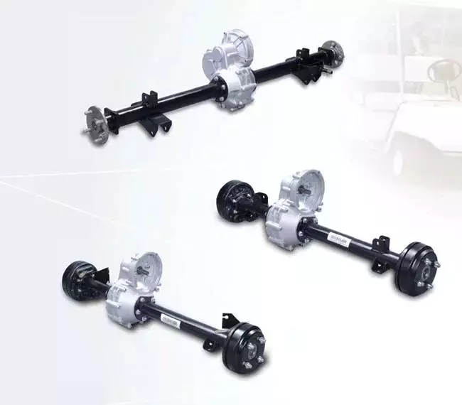
China Factory Supplied Trailer Parts 1850mm 16t German Bpw Axle for Sale
1. One-piece shaft tube, high strength, comfortable appearance.
2. Compared with other axles of the same load, it is light in weight and low in price.
3. Using non-asbestos friction plate, more environmentally friendly.
4. Adopting international general specifications, maintenance is convenient, fast and low cost.
Accessories
It adopts high-quality accessories from major brands at home and abroad, and global standard German
axle specifications. It has strong practicability, low price and convenient maintenance.
Axle
The factory produces its own shaft tube with quality assurance and cost advantage. The assembly process
strictly abides by international quality standards to create high-quality products.
Company Profile
Other Products
Certifications
The factory has obtained ISO9001 certification and Alibaba SGS certification, and has more
than a dozen patent certificates. It is a famous brand enterprise in China.
Customer Photos
Our company team participates in more than 10 exhibitions at home and abroad every year,
visiting and receiving customers dozens of times, and welcomes every customer’s inquiry and
factory inspection.
Packaging & Shipping
| Type: | Rear Axles |
|---|---|
| Certification: | ISO9001 |
| Loading Weight: | 16t |
| ABS: | With ABS |
| Tent Type: | Simple |
| Axle Number: | 3 |
| Samples: |
US$ 480/units
1 units(Min.Order) | |
|---|
| Customization: |
Available
| Customized Request |
|---|
Understanding the Working of an Axle
An axle is the central shaft of a rotating gear or wheel. It can be fixed to wheels or to the vehicle and can rotate along with them. The axle may include a number of bearings and other mounting points. Axles are essential for the operation of many types of vehicles. To understand the working of an axle, you should understand its basic purpose.
Vehicles with two axles
There are many different types of vehicles, but most are characterized by having two axles. Two axles are common in SUVs, trucks, and other vehicles that are meant to be off-road or for light hauling. Vehicles with two axles also include light-duty cargo vans and passenger cars.
There are many different kinds of two-axle vehicles, ranging from bicycles to motorcycles. In the United States, the most common kind of two-axle vehicles are pickup trucks, SUVs, and sedans. Three-axle vehicles are also common, with the largest type being tractor-trailers. Four-axle vehicles are rare, though. Some class 8 trucks have two-axle tractors.
Two-axle vehicles typically have two axles, with one axle supporting each of the two wheels. Other types of vehicles have three or four axles. The more axles a vehicle has, the more stability it has and the more weight it can handle. Two-axle vehicles are common, but three-axle vehicles are popular in transporting large cargo. Some are even designed with raised axles.
The number of axles on a car depends on its size and purpose. A car has a front axle and a rear axle. The front axle steers the vehicle, and the rear axle powers the wheels. The number of axles in a truck is largely dependent on its size and load, and some trucks have as many as four.
The front axle and rear axle are connected by a drive shaft. The driveshaft connects to the engine, which turns the axles. The two axles transfer the power from the engine to the wheels, and they may also help drive the vehicle. Axles are essential components of a vehicle, and should be strong and durable.
Axles are also important for a vehicle’s turning radius. Heavy-duty vehicles, such as semi-trucks, have large turning radii. Because they run across the width of the vehicle, axles make it possible for the wheels to turn freely. In addition to allowing the wheels to turn, they also support the weight of the vehicle.
Typical vehicles with two axles include the Toyota Rav4 and the Ford Mustang. The Rav4 uses two axles in front and rear-wheel drive. The Ford Mustang, on the other hand, has a live rear axle. In addition, the Mustang is also two axles. A tandem axle is an arrangement of two rear axles close together. It is a popular style in large vehicles.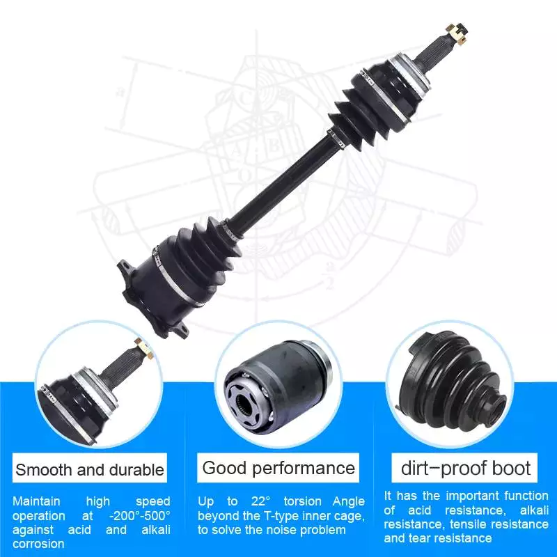
Vehicles with three axles
There are many different types of vehicles with three axles. Some of the most common include the dump truck, Greyhound bus, and tractor-trailer. Vehicles with three axles are generally heavier than four-axle vehicles. Vehicles with three axles have two sets of wheels – one front and one back. For example, a heavy truck will have three rear axles, a semi-trailer will have two front axles, and a tow truck will have two drive axles and two steer axles.
A vehicle’s axle count can vary. A simple method of figuring out the number of axles in a vehicle is to count the wheels. There are many ways to find out the number of axles on a vehicle. You can also look in the owner’s manual or ask a mechanic. If you’re unsure, ask someone who knows how to tell if a vehicle has three or four axles.
The design of a vehicle’s axles has several benefits. One of these benefits is its ability to disperse weight across a larger area, thereby reducing the risk of the vehicle sinking into soft ground. Dump trucks often drive to delivery sites with the third axle raised, lowering it only when it’s time to cross a soft area.
The number of axles in a vehicle is a crucial factor in determining how much power it needs to move. Different vehicles are designed to handle different terrains and have different axles to match their needs. For example, two-axle vehicles have two front axles, while three-axle vehicles have three rear axles.
A front axle is located at the front of the vehicle and helps with steering and processing road shocks. A front axle is often made of carbon steel, while a stub axle is a fixed axle that supports only one wheel. The front axle is connected to the stub axle through a kingpin.
Vehicles with three axles are generally larger than two axle vehicles. However, some two-axle vehicles can be three-axle, especially if they have a trailer. The design of a vehicle with three axles depends on what type of trailer it has. A two-axle trailer will usually have a trailer attached to it, and the rear axle will be responsible for moving power from the differential to the rear wheels.
Unlike semi-floating axles, full-floating axles are supported by two large bearings. They’re used for larger vehicles with high towing capacities. They also help with wheel alignment. A three-quarter floating axle is more complex than a semi-floating axle, and is often found in mid-size trucks.
There are also vehicles with a middle axle. Figures 2 and 3 illustrate this arrangement. The front and rear axles support most of the weight of the vehicle and the secondary axle has almost no ground weight. The secondary axle has a ground weight that is only 8.5% of the vehicle’s unloaded weight. The wheels of the vehicle remain in contact with the ground. Leaf spring 1 is coupled to the middle secondary axle.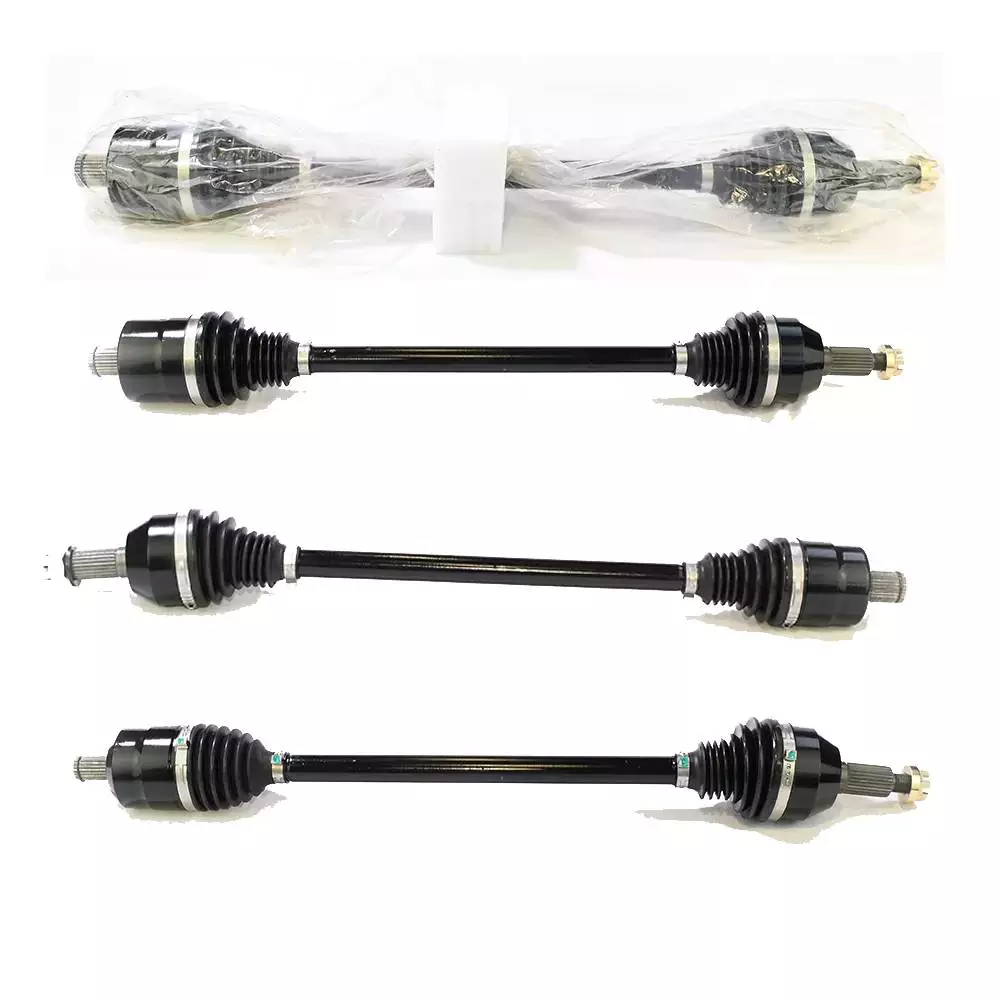
Types of axles
There are several different types of axles, and each is different in function. Some have bearings on each end, while others don’t. These two types of axles have different strengths and weaknesses, so it’s important to know which one is right for you. The best axle for your vehicle depends on your driving needs and budget.
The most basic type of axle is the axle shaft. This is the most inexpensive kind of axle. It connects the wheel hub to the axle shaft. The axle shaft is attached to the wheel hub by bolts. The wheel axle sits in the middle of the axle shaft. The bearings and axle casing transfer the weight of the wheel to the axle. The bearings are designed to distribute the weight evenly on both sides of the axle.
Another type of axle is the reverse Czpt stub axle. It is similar to the standard Czpt stub axle, but the reverse Czpt is designed with an L-shaped spindle. The rear axles also come in different types. These depend on how they are mounted on the vehicle. There are three different types of rear axles: rigid axles, semi-floating axles, and floating axles.
A full floating axle, on the other hand, does not support the weight of the vehicle. It is attached to the wheel hub and axle housing. It is most common in trucks and heavy duty vehicles. These axles are also the most durable, but they can only handle a heavy load. If the axle shaft breaks or is damaged, the vehicle will drop.
The type of axles a vehicle has is important because it affects the turning radius. A single axle vehicle has one drive axle at the rear, while a tandem vehicle has two drives. This means that the vehicle has a larger turning radius than a single axle one. There are also a variety of designs that allow it to turn at higher speeds and with less torque.
Lastly, a dead front axle is an immovable front axle, not revolving with the wheels. It is protected by housings and is a good choice for vehicles that cannot be driven in wet conditions. They provide the driving power from the Axles to the front wheels. The Czpt type uses a kingpin, while the Lamoine type uses a yoke-type hinge.
Three quarter floating axles are a hybrid between a full and semi floating axle. In this type, the axle is attached to the hub through bearings. As a result, it eliminates the shearing stress of the axle and focuses on bending loads. These axles are cheaper than the semi-floating type, and they are used in lighter trucks.
A semi-floating axle, on the other hand, has a bearing inside its axle casing. This axle is a lightweight option that still supports all the vehicle’s weight. This axle is generally used on light-duty pickups and mid-size trucks.

editor by CX 2023-05-05
China OEM Wheel Hub Bearing & Assembly for Hyundai Santa Fe 51750-3J000, 513266 with high quality
Product Description
Contact:; Joanna Xuan
Mob:; +86~8 13858117
Wheel hub bearing for Hyundai Santa Fe 51750-3J
Stiffness and Torsional Vibration of Spline-Couplings
In this paper, we describe some basic characteristics of spline-coupling and examine its torsional vibration behavior. We also explore the effect of spline misalignment on rotor-spline coupling. These results will assist in the design of improved spline-coupling systems for various applications. The results are presented in Table 1.
Stiffness of spline-coupling
The stiffness of a spline-coupling is a function of the meshing force between the splines in a rotor-spline coupling system and the static vibration displacement. The meshing force depends on the coupling parameters such as the transmitting torque and the spline thickness. It increases nonlinearly with the spline thickness.
A simplified spline-coupling model can be used to evaluate the load distribution of splines under vibration and transient loads. The axle spline sleeve is displaced a z-direction and a resistance moment T is applied to the outer face of the sleeve. This simple model can satisfy a wide range of engineering requirements but may suffer from complex loading conditions. Its asymmetric clearance may affect its engagement behavior and stress distribution patterns.
The results of the simulations show that the maximum vibration acceleration in both Figures 10 and 22 was 3.03 g/s. This results indicate that a misalignment in the circumferential direction increases the instantaneous impact. Asymmetry in the coupling geometry is also found in the meshing. The right-side spline’s teeth mesh tightly while those on the left side are misaligned.
Considering the spline-coupling geometry, a semi-analytical model is used to compute stiffness. This model is a simplified form of a classical spline-coupling model, with submatrices defining the shape and stiffness of the joint. As the design clearance is a known value, the stiffness of a spline-coupling system can be analyzed using the same formula.
The results of the simulations also show that the spline-coupling system can be modeled using MASTA, a high-level commercial CAE tool for transmission analysis. In this case, the spline segments were modeled as a series of spline segments with variable stiffness, which was calculated based on the initial gap between spline teeth. Then, the spline segments were modelled as a series of splines of increasing stiffness, accounting for different manufacturing variations. The resulting analysis of the spline-coupling geometry is compared to those of the finite-element approach.
Despite the high stiffness of a spline-coupling system, the contact status of the contact surfaces often changes. In addition, spline coupling affects the lateral vibration and deformation of the rotor. However, stiffness nonlinearity is not well studied in splined rotors because of the lack of a fully analytical model.
Characteristics of spline-coupling
The study of spline-coupling involves a number of design factors. These include weight, materials, and performance requirements. Weight is particularly important in the aeronautics field. Weight is often an issue for design engineers because materials have varying dimensional stability, weight, and durability. Additionally, space constraints and other configuration restrictions may require the use of spline-couplings in certain applications.
The main parameters to consider for any spline-coupling design are the maximum principal stress, the maldistribution factor, and the maximum tooth-bearing stress. The magnitude of each of these parameters must be smaller than or equal to the external spline diameter, in order to provide stability. The outer diameter of the spline must be at least 4 inches larger than the inner diameter of the spline.
Once the physical design is validated, the spline coupling knowledge base is created. This model is pre-programmed and stores the design parameter signals, including performance and manufacturing constraints. It then compares the parameter values to the design rule signals, and constructs a geometric representation of the spline coupling. A visual model is created from the input signals, and can be manipulated by changing different parameters and specifications.
The stiffness of a spline joint is another important parameter for determining the spline-coupling stiffness. The stiffness distribution of the spline joint affects the rotor’s lateral vibration and deformation. A finite element method is a useful technique for obtaining lateral stiffness of spline joints. This method involves many mesh refinements and requires a high computational cost.
The diameter of the spline-coupling must be large enough to transmit the torque. A spline with a larger diameter may have greater torque-transmitting capacity because it has a smaller circumference. However, the larger diameter of a spline is thinner than the shaft, and the latter may be more suitable if the torque is spread over a greater number of teeth.
Spline-couplings are classified according to their tooth profile along the axial and radial directions. The radial and axial tooth profiles affect the component’s behavior and wear damage. Splines with a crowned tooth profile are prone to angular misalignment. Typically, these spline-couplings are oversized to ensure durability and safety.
Stiffness of spline-coupling in torsional vibration analysis
This article presents a general framework for the study of torsional vibration caused by the stiffness of spline-couplings in aero-engines. It is based on a previous study on spline-couplings. It is characterized by the following 3 factors: bending stiffness, total flexibility, and tangential stiffness. The first criterion is the equivalent diameter of external and internal splines. Both the spline-coupling stiffness and the displacement of splines are evaluated by using the derivative of the total flexibility.
The stiffness of a spline joint can vary based on the distribution of load along the spline. Variables affecting the stiffness of spline joints include the torque level, tooth indexing errors, and misalignment. To explore the effects of these variables, an analytical formula is developed. The method is applicable for various kinds of spline joints, such as splines with multiple components.
Despite the difficulty of calculating spline-coupling stiffness, it is possible to model the contact between the teeth of the shaft and the hub using an analytical approach. This approach helps in determining key magnitudes of coupling operation such as contact peak pressures, reaction moments, and angular momentum. This approach allows for accurate results for spline-couplings and is suitable for both torsional vibration and structural vibration analysis.
The stiffness of spline-coupling is commonly assumed to be rigid in dynamic models. However, various dynamic phenomena associated with spline joints must be captured in high-fidelity drivetrain models. To accomplish this, a general analytical stiffness formulation is proposed based on a semi-analytical spline load distribution model. The resulting stiffness matrix contains radial and tilting stiffness values as well as torsional stiffness. The analysis is further simplified with the blockwise inversion method.
It is essential to consider the torsional vibration of a power transmission system before selecting the coupling. An accurate analysis of torsional vibration is crucial for coupling safety. This article also discusses case studies of spline shaft wear and torsionally-induced failures. The discussion will conclude with the development of a robust and efficient method to simulate these problems in real-life scenarios.
Effect of spline misalignment on rotor-spline coupling
In this study, the effect of spline misalignment in rotor-spline coupling is investigated. The stability boundary and mechanism of rotor instability are analyzed. We find that the meshing force of a misaligned spline coupling increases nonlinearly with spline thickness. The results demonstrate that the misalignment is responsible for the instability of the rotor-spline coupling system.
An intentional spline misalignment is introduced to achieve an interference fit and zero backlash condition. This leads to uneven load distribution among the spline teeth. A further spline misalignment of 50um can result in rotor-spline coupling failure. The maximum tensile root stress shifted to the left under this condition.
Positive spline misalignment increases the gear mesh misalignment. Conversely, negative spline misalignment has no effect. The right-handed spline misalignment is opposite to the helix hand. The high contact area is moved from the center to the left side. In both cases, gear mesh is misaligned due to deflection and tilting of the gear under load.
This variation of the tooth surface is measured as the change in clearance in the transverse plain. The radial and axial clearance values are the same, while the difference between the 2 is less. In addition to the frictional force, the axial clearance of the splines is the same, which increases the gear mesh misalignment. Hence, the same procedure can be used to determine the frictional force of a rotor-spline coupling.
Gear mesh misalignment influences spline-rotor coupling performance. This misalignment changes the distribution of the gear mesh and alters contact and bending stresses. Therefore, it is essential to understand the effects of misalignment in spline couplings. Using a simplified system of helical gear pair, Hong et al. examined the load distribution along the tooth interface of the spline. This misalignment caused the flank contact pattern to change. The misaligned teeth exhibited deflection under load and developed a tilting moment on the gear.
The effect of spline misalignment in rotor-spline couplings is minimized by using a mechanism that reduces backlash. The mechanism comprises cooperably splined male and female members. One member is formed by 2 coaxially aligned splined segments with end surfaces shaped to engage in sliding relationship. The connecting device applies axial loads to these segments, causing them to rotate relative to 1 another.


China OEM 515065 Wheel Bearing and Hub Assembly for Nissan with Good quality
Product Description
1.Model:515065,45712-EA3
How to Calculate Stiffness, Centering Force, Wear and Fatigue Failure of Spline Couplings
There are various types of spline couplings. These couplings have several important properties. These properties are: Stiffness, Involute splines, Misalignment, Wear and fatigue failure. To understand how these characteristics relate to spline couplings, read this article. It will give you the necessary knowledge to determine which type of coupling best suits your needs. Keeping in mind that spline couplings are usually spherical in shape, they are made of steel.
Involute splines
An effective side interference condition minimizes gear misalignment. When 2 splines are coupled with no spline misalignment, the maximum tensile root stress shifts to the left by 5 mm. A linear lead variation, which results from multiple connections along the length of the spline contact, increases the effective clearance or interference by a given percentage. This type of misalignment is undesirable for coupling high-speed equipment.
Involute splines are often used in gearboxes. These splines transmit high torque, and are better able to distribute load among multiple teeth throughout the coupling circumference. The involute profile and lead errors are related to the spacing between spline teeth and keyways. For coupling applications, industry practices use splines with 25 to 50-percent of spline teeth engaged. This load distribution is more uniform than that of conventional single-key couplings.
To determine the optimal tooth engagement for an involved spline coupling, Xiangzhen Xue and colleagues used a computer model to simulate the stress applied to the splines. The results from this study showed that a “permissible” Ruiz parameter should be used in coupling. By predicting the amount of wear and tear on a crowned spline, the researchers could accurately predict how much damage the components will sustain during the coupling process.
There are several ways to determine the optimal pressure angle for an involute spline. Involute splines are commonly measured using a pressure angle of 30 degrees. Similar to gears, involute splines are typically tested through a measurement over pins. This involves inserting specific-sized wires between gear teeth and measuring the distance between them. This method can tell whether the gear has a proper tooth profile.
The spline system shown in Figure 1 illustrates a vibration model. This simulation allows the user to understand how involute splines are used in coupling. The vibration model shows 4 concentrated mass blocks that represent the prime mover, the internal spline, and the load. It is important to note that the meshing deformation function represents the forces acting on these 3 components.
Stiffness of coupling
The calculation of stiffness of a spline coupling involves the measurement of its tooth engagement. In the following, we analyze the stiffness of a spline coupling with various types of teeth using 2 different methods. Direct inversion and blockwise inversion both reduce CPU time for stiffness calculation. However, they require evaluation submatrices. Here, we discuss the differences between these 2 methods.
The analytical model for spline couplings is derived in the second section. In the third section, the calculation process is explained in detail. We then validate this model against the FE method. Finally, we discuss the influence of stiffness nonlinearity on the rotor dynamics. Finally, we discuss the advantages and disadvantages of each method. We present a simple yet effective method for estimating the lateral stiffness of spline couplings.
The numerical calculation of the spline coupling is based on the semi-analytical spline load distribution model. This method involves refined contact grids and updating the compliance matrix at each iteration. Hence, it consumes significant computational time. Further, it is difficult to apply this method to the dynamic analysis of a rotor. This method has its own limitations and should be used only when the spline coupling is fully investigated.
The meshing force is the force generated by a misaligned spline coupling. It is related to the spline thickness and the transmitting torque of the rotor. The meshing force is also related to the dynamic vibration displacement. The result obtained from the meshing force analysis is given in Figures 7, 8, and 9.
The analysis presented in this paper aims to investigate the stiffness of spline couplings with a misaligned spline. Although the results of previous studies were accurate, some issues remained. For example, the misalignment of the spline may cause contact damages. The aim of this article is to investigate the problems associated with misaligned spline couplings and propose an analytical approach for estimating the contact pressure in a spline connection. We also compare our results to those obtained by pure numerical approaches.
Misalignment
To determine the centering force, the effective pressure angle must be known. Using the effective pressure angle, the centering force is calculated based on the maximum axial and radial loads and updated Dudley misalignment factors. The centering force is the maximum axial force that can be transmitted by friction. Several published misalignment factors are also included in the calculation. A new method is presented in this paper that considers the cam effect in the normal force.
In this new method, the stiffness along the spline joint can be integrated to obtain a global stiffness that is applicable to torsional vibration analysis. The stiffness of bearings can also be calculated at given levels of misalignment, allowing for accurate estimation of bearing dimensions. It is advisable to check the stiffness of bearings at all times to ensure that they are properly sized and aligned.
A misalignment in a spline coupling can result in wear or even failure. This is caused by an incorrectly aligned pitch profile. This problem is often overlooked, as the teeth are in contact throughout the involute profile. This causes the load to not be evenly distributed along the contact line. Consequently, it is important to consider the effect of misalignment on the contact force on the teeth of the spline coupling.
The centre of the male spline in Figure 2 is superposed on the female spline. The alignment meshing distances are also identical. Hence, the meshing force curves will change according to the dynamic vibration displacement. It is necessary to know the parameters of a spline coupling before implementing it. In this paper, the model for misalignment is presented for spline couplings and the related parameters.
Using a self-made spline coupling test rig, the effects of misalignment on a spline coupling are studied. In contrast to the typical spline coupling, misalignment in a spline coupling causes fretting wear at a specific position on the tooth surface. This is a leading cause of failure in these types of couplings.
Wear and fatigue failure
The failure of a spline coupling due to wear and fatigue is determined by the first occurrence of tooth wear and shaft misalignment. Standard design methods do not account for wear damage and assess the fatigue life with big approximations. Experimental investigations have been conducted to assess wear and fatigue damage in spline couplings. The tests were conducted on a dedicated test rig and special device connected to a standard fatigue machine. The working parameters such as torque, misalignment angle, and axial distance have been varied in order to measure fatigue damage. Over dimensioning has also been assessed.
During fatigue and wear, mechanical sliding takes place between the external and internal splines and results in catastrophic failure. The lack of literature on the wear and fatigue of spline couplings in aero-engines may be due to the lack of data on the coupling’s application. Wear and fatigue failure in splines depends on a number of factors, including the material pair, geometry, and lubrication conditions.
The analysis of spline couplings shows that over-dimensioning is common and leads to different damages in the system. Some of the major damages are wear, fretting, corrosion, and teeth fatigue. Noise problems have also been observed in industrial settings. However, it is difficult to evaluate the contact behavior of spline couplings, and numerical simulations are often hampered by the use of specific codes and the boundary element method.
The failure of a spline gear coupling was caused by fatigue, and the fracture initiated at the bottom corner radius of the keyway. The keyway and splines had been overloaded beyond their yield strength, and significant yielding was observed in the spline gear teeth. A fracture ring of non-standard alloy steel exhibited a sharp corner radius, which was a significant stress raiser.
Several components were studied to determine their life span. These components include the spline shaft, the sealing bolt, and the graphite ring. Each of these components has its own set of design parameters. However, there are similarities in the distributions of these components. Wear and fatigue failure of spline couplings can be attributed to a combination of the 3 factors. A failure mode is often defined as a non-linear distribution of stresses and strains.